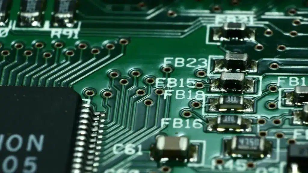

A printed circuit board, or PCB, is the main base in every electronic device you use. You see a circuit board as a flat, thin board made from material that does not conduct electricity, often fiberglass. Copper traces run on the surface and make paths that connect electronic parts. These copper lines act like tiny roads. They let electrical signals move between parts like resistors and integrated circuits. The circuit board keeps each part in place and connects them so the device can work. You find printed circuit boards in almost every modern device, from your phone to your computer.
Key Takeaways
A printed circuit board (PCB) holds and links all electronic parts in devices. It lets electricity move so the device can work.
PCBs have layers like copper that make paths for electricity. They also have a strong base that gives support. There are coatings that protect the board from harm.
There are different PCB types like single-sided, double-sided, and multilayer boards. Each type fits different devices and how hard they are to build.
Picking the right materials and design helps PCBs deal with heat, signals, and size. This makes devices smaller and more dependable.
PCBs are in almost every modern device, like phones and cars. They help power the technology that keeps our lives running well.
What Is a Printed Circuit Board
PCB Basics
If you open any electronic device, you will see a circuit board inside. This board is the main place where all the electronic parts connect and stay in place. Copper traces run across the board and make paths for electricity. These traces take the place of messy wires and help the device work better. The printed circuit board holds things like resistors, capacitors, and integrated circuits. The board keeps everything neat and helps all the parts work together.
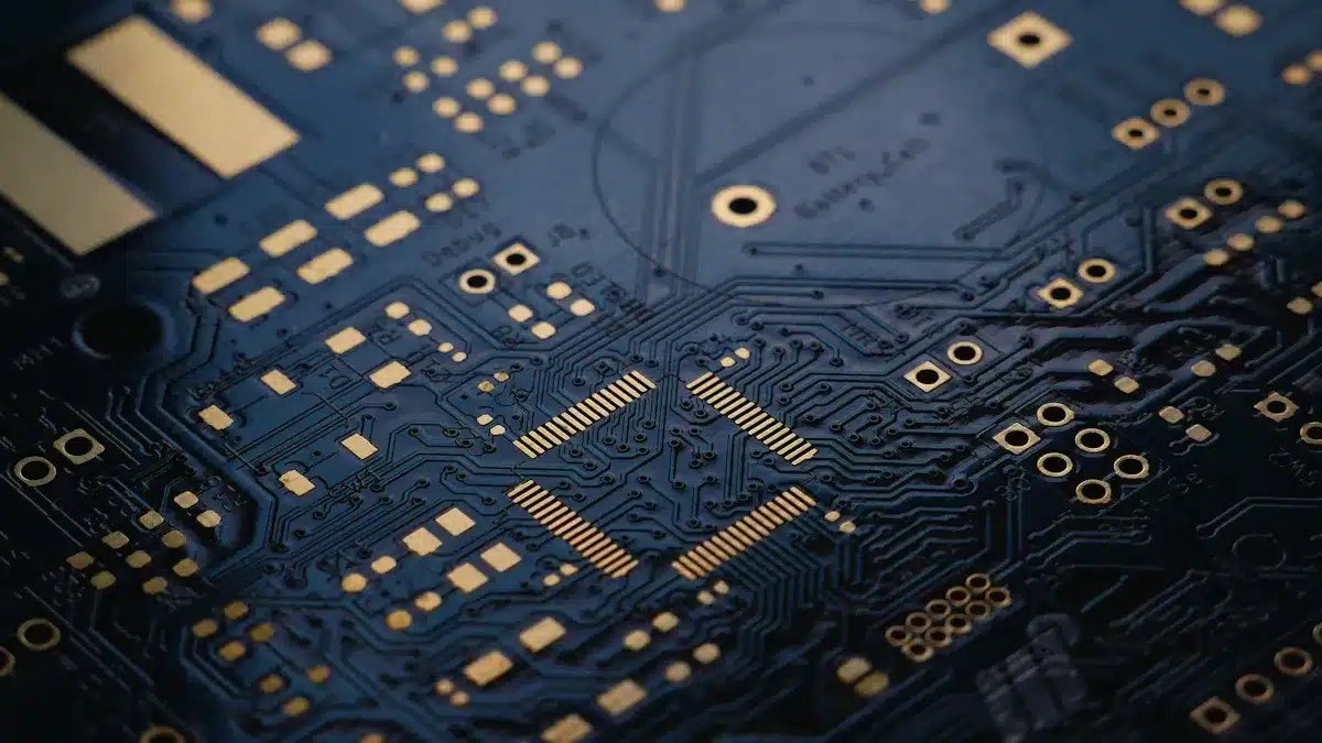
A printed circuit board is made of layers that conduct and insulate. The copper layers are like roads for electricity. The base, often fiberglass or epoxy, gives the board strength. There are pads for mounting parts and vias to connect layers. Silkscreen markings help you find parts easily. When designing a PCB, you need to put parts in good spots for signal flow, power, and heat. You must plan how each part fits and connects so the board works well and stays strong.
Tip: When you design a PCB, keep important traces short. Use ground planes to lower noise. Good heat control stops your device from getting too hot.
PCB Structure
A circuit board has several layers, and each one has a job. Here is a simple table that shows the main layers and what they are made of:
Layer Type | Typical Materials and Description |
|---|---|
Substrate | FR-4 (glass-reinforced epoxy), phenolics, ceramic-based materials, flexible materials like polyimide, PTFE, PEEK |
Copper Layer | Thin copper foil laminated on substrate, used for electrical conduction |
Soldermask Layer | Protective layer above copper to prevent solder bridging, usually green |
Silkscreen Layer | Printed layer on top of soldermask for component identification, usually white |
The copper layer is the main path for electricity. The substrate gives the board strength. The soldermask protects the copper and stops short circuits. The silkscreen helps you find and place parts. Some boards use extra layers like prepreg and laminate to hold everything together and add insulation.
If a circuit board is used in a tough place, like a factory or a car, it needs strong materials. Ceramic-based substrates and flexible materials like polyimide help the board last longer and work better in hard conditions.
PCB Function
You might ask, what do PCBs do? They connect electronic parts and let your device work. Copper traces guide electricity from one part to another. Resistors control current, capacitors store energy, and integrated circuits do hard jobs. Diodes let current go one way and protect your device. Connectors link the board to other devices. Power sources give the energy needed to run.
Printed circuit boards work better and are stronger than old wiring methods. You get smaller designs, better signal paths, and strong support for all parts. PCB design uses things like microvias and fine lines to fit more connections in a small space. You get good signal flow, less interference, and easier assembly. The board makes sure your device gets the right voltage and current, keeping it safe and working well.
You find printed circuit boards in phones, computers, home appliances, and cars.
PCBs help LED lights work, control machines, and manage safety in cars.
The design and layers of the board allow fast data, power control, and signal handling.
When you use a device, you count on the printed circuit board to connect, support, and protect all the parts. The PCB is like the backbone, making sure every signal goes where it should and every part works together.
PCB Components and Materials
Main PCB Components
When you look at a printed circuit board, you see many parts. Each part has its own job. You find passive components like resistors, capacitors, and inductors. These parts control current, store energy, and filter signals. Active components include transistors and integrated circuits. They process and make signals stronger. Electromechanical parts are things like connectors and switches. These let you use the device or link it to other things.
Here is a table that lists common pcb components and what they do:
Component | Primary Function | Typical Use Case |
|---|---|---|
Resistors | Limit current, divide voltage | LED circuits, biasing |
Capacitors | Store energy, filter signals | Power smoothing, timing |
Inductors | Store magnetic energy | Power supplies, RF circuits |
Diodes | Direct current flow, protect circuits | Rectifiers, LED drivers |
Transistors | Amplify or switch signals | Logic circuits, motor control |
Integrated Circuits (ICs) | Miniaturized circuit functions | Microcontrollers, amplifiers |
Connectors | External interfacing | USB ports, sensors, battery inputs |
Crystals | Provide clock signals | Timers, communications |
Switches | User input, state control | Buttons, toggles |
Fuses | Protect from overcurrent | Power supply, sensitive circuits |
Tip: Passive parts shape signals and set levels. Active parts control and change signals. Electromechanical parts connect your board to other things.
You see copper conductors on the board. These connect all the parts and let signals move between them. The copper lines are like main roads for electricity. They help each part do its job.
PCB Materials
You need strong materials to make a printed circuit board. The most common base is FR-4. It is made from fiberglass and epoxy resin. FR-4 gives good insulation, strength, and stops fire. It works well for most devices, like phones and computers.
Other materials are CEM-1 and CEM-3. These cost less and are used for simple boards. Ceramic substrates like aluminum oxide and aluminum nitride move heat well. They work in high-power or high-frequency circuits. Polyimide and PTFE are flexible and resist heat and chemicals. These are good for wearable or tough environments.
Here is a table that lists popular PCB materials and their main features:
Material | Composition | Key Properties & Suitability |
|---|---|---|
FR-4 | Epoxy resin + woven fiberglass | Strong, flame retardant, good insulation, affordable |
CEM-1 | Epoxy resin + paper core | Low cost, moderate strength, single-sided boards |
CEM-3 | Epoxy resin + woven fiberglass | Cost-effective, supports double-sided boards |
Ceramic | Aluminum oxide, aluminum nitride | High thermal conductivity, stable at high temperatures |
Polyimide | Flexible polymer | Flexible, heat and chemical resistant |
PTFE | Synthetic polymer | Low dielectric loss, stable at high frequencies |
You must pick the right material for your device. FR-4 works for most things. Ceramic and flexible materials help in hard or high-frequency jobs. The copper lines give great paths for electricity. The base material decides how well your board handles heat, stress, and signals.
Note: Picking the right PCB material helps signals stay clear, controls heat, and makes your device last longer. Flexible materials let you make small, bendy devices. Ceramic substrates keep high-power circuits cool and steady.
Printed Circuit Board Types
Single-Sided, Double-Sided, Multilayer
There are different kinds of circuit boards. Each type has its own use. A single-sided circuit board has copper tracks on one side only. This design is simple and used in basic electronics. You see it in calculators, cameras, and power supplies. It costs less but cannot hold many parts. Complex circuits do not fit well on it.
A double-sided circuit board has copper layers on both sides. Small holes called vias connect the layers. This lets you add more parts and make harder circuits. Devices like LED lights, amplifiers, and car dashboards use double-sided boards. You get better signal flow and more ways to connect things.
Multilayer circuit boards have three or more copper layers. Insulating material separates each layer. Some boards have up to twelve layers or even more. You can fit lots of connections in a small space. These boards are used in smartphones, GPS, and science tools. They give high performance and keep signals strong. Designs can be very compact.
PCB Type | Typical Devices / Applications |
|---|---|
Single-sided | Cameras, calculators, printers, power supplies |
Double-sided | LED lighting, amplifiers, car dashboards, industrial controls |
Multilayer | Smartphones, GPS, fiber optics, heart monitors, scientific tools |
Note: When you go from single-sided to multilayer, boards get more complex. They can handle more advanced electronics.
Rigid, Flexible, Rigid-Flex
You also pick the right structure for your board. Rigid boards use a hard base like FR-4 fiberglass. They keep their shape and do not bend. Most phones, computers, and machines use rigid boards. They are strong and work well.
Flexible circuit boards use a bendable base like polyimide. You can fold or twist these boards to fit small spaces. Medical devices, wearables, and aerospace gear use flexible boards. They are light and save space. You must follow special rules so the layers do not break.
Rigid-flex circuit boards mix both types. Some parts are hard, and some can bend. This lets you make three-dimensional layouts. You see rigid-flex boards in advanced cameras and small electronics. They give both strength and flexibility.
Here is a table to help you compare:
Type | Structure & Materials | Key Applications |
|---|---|---|
Rigid | Solid FR-4, fixed shape | Phones, computers, cars |
Flexible | Polyimide, bendable, thin | Wearables, medical, aerospace |
Rigid-Flex | Mix of rigid and flexible sections | Cameras, military, complex electronics |
Rigid boards are strong and easy to put together.
Flexible boards fit into tiny or moving spaces.
Rigid-flex boards save space and need fewer connectors.
Tip: Always match the board type and layers to your device’s needs. This choice changes the size, strength, and how well it works.
PCB Design and Manufacturing
PCB Design Steps
You start the pcb design process by understanding what your circuit needs to do. You look at the electrical requirements, such as voltage, current, and signal types. Next, you create a schematic that shows how each part connects. You use special software to turn this schematic into a layout for your pcb. Here are the main steps you follow:
Define your goals and make a block diagram for your pcb.
Draw the schematic and list all the parts you need.
Place each component in the best spot for signal flow and heat control.
Design the stackup, which means deciding how many layers your pcb will have.
Set rules for trace width, spacing, and other pcb design considerations.
Add drill holes and route the traces to connect everything.
Run design rule checks to catch errors.
Add labels and reference marks.
Prepare files for the pcb manufacturing process and quick pcb prototyping.
Tip: Careful pcb design helps you avoid mistakes that could cause your circuit to fail.
PCB Manufacturing
After you finish your pcb design, you move to manufacturing. The pcb manufacturing process uses advanced machines and chemicals to make your board. You start by printing your design onto the base material. Then, you etch away extra copper, drill holes, and plate them for strong connections. Solder mask and silkscreen layers protect and label your pcb. Automated Optical Inspection (AOI) checks for defects. Quality control steps, like stress testing and visual checks, help prevent early failures and make sure your pcb meets industry standards.
Assembly Process
Circuit board assembly puts all the parts onto your pcb. Automated pick-and-place machines set each component in the right spot. Reflow soldering melts solder paste to make solid joints. Inspections using AOI and X-ray catch any problems early. You test the finished board to make sure it works as planned. Cleaning removes any leftover flux or dirt. Good assembly practices, like using quality parts and careful soldering, keep your pcb reliable. If you face challenges, such as tiny parts or heat issues, you use special tools and techniques to solve them. This careful process ensures your circuit board assembly works well in your device.
Printed Circuit Boards in Electronics
Everyday Devices
Circuit boards are in many things you use every day. Your smartphone, tablet, and computer all need a pcb to work. Televisions, gaming consoles, and recording devices use circuit boards for fast signals. In the kitchen, blenders and coffee makers use them to control speed and time. Cars have printed circuit boards for navigation, engine control, music, and LED lights. Medical devices like heart monitors and CT scan machines need a pcb for safe and correct readings. Security systems, such as electronic locks and smoke detectors, use circuit boards to help keep you safe.
Here is a quick list of everyday devices that use circuit boards:
Smartphones and tablets
Computers and televisions
Blenders and coffee makers
Gaming consoles and recording devices
Heart monitors and CT scan machines
Electronic locks and smoke detectors
You use these devices all the time. The circuit board inside helps signals move fast and parts work together. If you ask, “what are printed circuit boards used for?” the answer is almost every device around you.
Importance in Technology
You may wonder why circuit boards are so important in technology. The pcb is like the nervous system for your device. It connects all the parts and lets them share information. Better pcb design has made devices smaller, faster, and stronger. Miniaturization lets you carry a phone or wear a health monitor. Flexible and rigid-flex pcbs make new shapes and foldable gadgets possible.
Here are some ways pcb technology drives innovation:
PCBs make small, strong connections between electronic parts.
New designs help devices get smaller and do more.
High-density circuit boards fit more features in less space.
Flexible pcbs help make wearables and foldable screens.
Automated manufacturing keeps devices cheap and reliable.
Modern printed circuit board applications include smart homes, driverless cars, and medical equipment.
You see printed circuit boards in every new gadget. If you ask, “what are printed circuit boards used for?” you find they power the future of technology. Printed circuit board applications keep growing as engineers make devices smarter and more connected.
Tip: Next time you use your phone or start your car, remember the circuit board inside makes it all work.
You have learned that a pcb holds and links all the parts in your favorite gadgets. These boards help make electronics smaller, tougher, and work better.
PCBs keep connections neat, stop short circuits, and make it cheaper to build lots of devices.
You see them in things like smartphones, medical tools, and cars.
When you know what a printed circuit board does, you can see why your devices work well and last longer.
FAQ
What is the main job of a printed circuit board?
You use a printed circuit board to hold and connect all the electronic parts in your device. The board lets electricity flow between parts so your device can work.
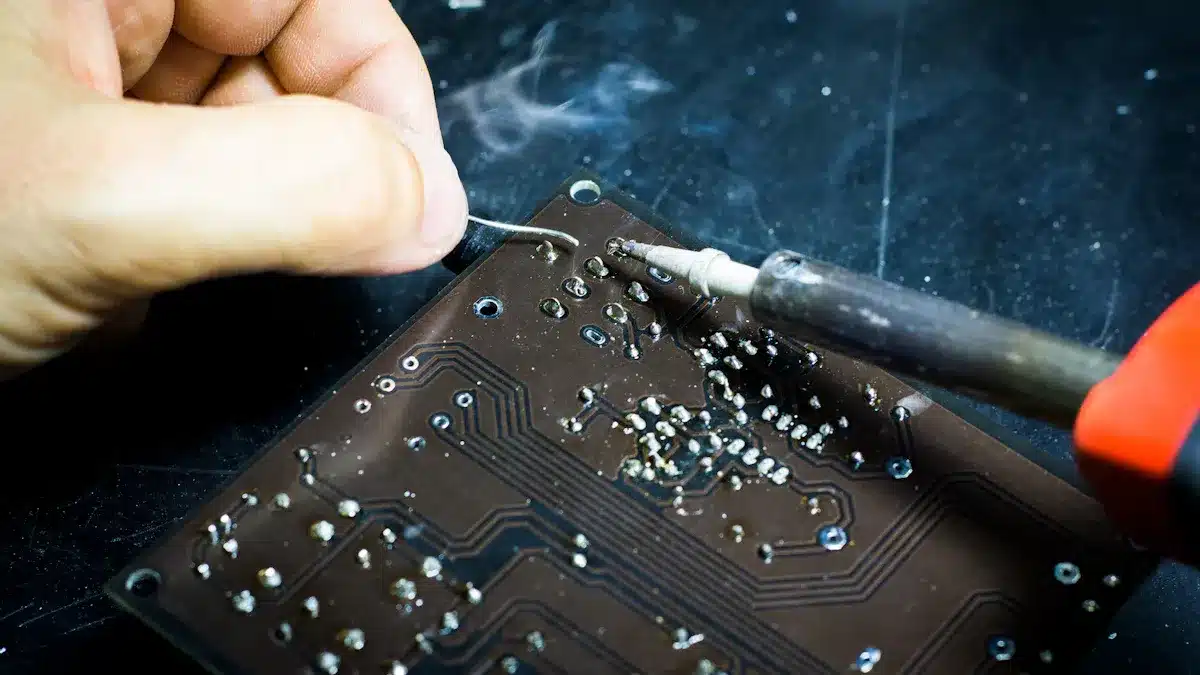
Can you repair a damaged PCB?
You can fix some simple problems, like broken traces or loose parts. For big damage, you often need to replace the whole board. Always check for burnt spots or broken lines.
Why do PCBs have different colors?
You see different colors because of the soldermask layer. Green is common, but you also find red, blue, black, or white. The color does not change how the board works.
How do you keep a PCB safe from damage?
Keep your PCB dry and clean. Avoid bending or dropping it. Use anti-static bags when you store or move boards. Handle the board by the edges to prevent static shock.
What tools do you need to work with PCBs?
Tool | Use |
|---|---|
Soldering iron | Attach parts to the board |
Multimeter | Test connections |
Tweezers | Place small parts |
Screwdriver | Open device cases |
You use these tools to build, test, or repair circuit boards.
See Also
Exploring The Meaning And Importance Of PCBA In Electronics
Defining PCBA And Its Function Within Electronic Devices
Understanding What PCBA Is And Its Critical Role In Electronics