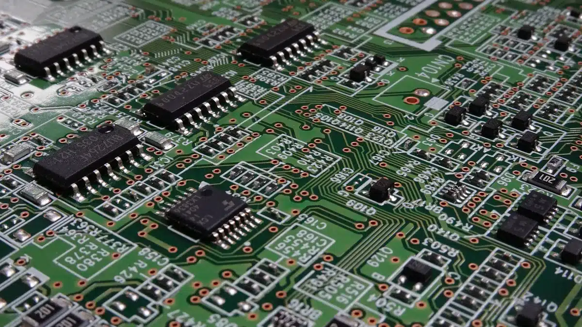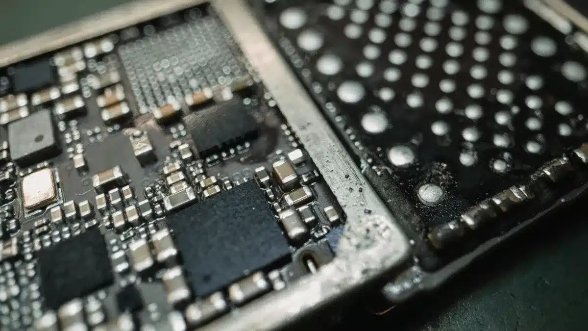
Printed circuit boards require several essential materials, and understanding how are printed circuit boards made involves knowing these key components. The main PCB materials include the substrate, copper layer, resin, solder mask, and silkscreen. Common PCB substrate materials such as FR-4, polyimide, phenolic paper, metal-core, and PTFE incorporate glass, fiberglass, and resin. These materials provide the board with strength and prevent electricity from leaking. The copper layer creates pathways for electrical signals, while the resin binds the glass fibers together and maintains the board’s shape. The solder mask covers the copper traces to prevent corrosion and makes assembly easier. Silkscreen adds labels to the board, indicating where parts like resistors and capacitors should be placed. All these materials play a crucial role in how are printed circuit boards made, supporting vital components like copper, glass, resistors, and capacitors. Different PCB materials are chosen based on the electrical requirements, whether for simple circuits or more advanced designs. The common PCB layers and materials ensure that boards are safe, durable, and reliable.
Key Takeaways
Printed circuit boards need important materials like substrate, copper, solder mask, and silkscreen. These materials help make circuits strong, safe, and reliable.
Picking the right substrate is important. FR-4 is good for most uses. Polyimide works for boards that need to bend or handle heat. This helps the PCB do its job well.
Copper layers make paths for electricity. Solder masks keep these paths safe from harm and stops shorts when building the board.
Each PCB material has special uses. Metal-core boards help cool parts that get hot. PTFE is good for signals that need high frequency. Phenolic paper is used for simple and cheap boards.
Choosing PCB materials depends on heat, signal needs, cost, and where the board will be used. This helps the board last longer and work better for its job.
PCB Structure and How Are Printed Circuit Boards Made

Printed circuit boards have layers. These layers make the board strong and useful. To know how are printed circuit boards made, you need to learn what each material does.
Substrate Materials
The substrate is the base of every printed circuit board. Most makers use FR-4 for the substrate. FR-4 is a glass-reinforced epoxy. Some boards use polyimide if they need to bend or handle heat. The substrate gives support and keeps electricity from leaking. It separates copper layers and holds the board steady. The substrate also helps with heat and stops fire from spreading. In pcb manufacturing, the substrate is cut first. The substrate is important for making the board last long.
Common pcb layers in a board are:
Core substrate: This is the main layer that insulates.
Copper foil: This is put on the substrate to make circuits.
Prepreg: This layer bonds and insulates other layers.
Solder mask layer: This layer protects copper traces.
Silkscreen layer: This layer adds labels and marks.
Copper Layer
The copper layer makes paths for signals and power. Makers put thin copper foil on the substrate. They use photoresist and UV light to make the circuit shape. Chemicals remove extra copper and leave the right paths. Multilayer boards have many copper layers with substrate between them. Copper makes traces, power planes, and ground planes. These layers help connect parts and move heat away. Copper is also used to coat holes so layers can connect.
Solder Mask
The solder mask covers copper traces to keep them safe. It stops rust and keeps solder from touching the wrong spots. Makers put liquid solder mask over the copper layer. UV light hardens the mask where needed. The rest is washed off. The solder mask is usually green but can be other colors. This layer makes the board stronger and helps with assembly by stopping shorts.
Silkscreen
The silkscreen layer prints labels and outlines on the board. Makers use silkscreen ink after the solder mask is done. The silkscreen shows where parts go and helps people build the board. It can show logos, warnings, and part numbers.
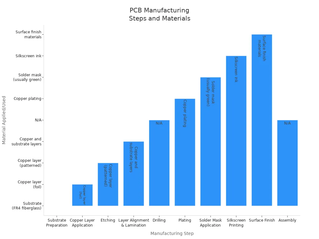
Here is a table that shows the main steps in how are printed circuit boards made and when each material is used:
Manufacturing Step | Description | Material Applied/Used | |
|---|---|---|---|
1 | Substrate Preparation | The substrate layer is prepared as the base of the PCB. | Substrate (FR-4 fiberglass) |
2-3 | Copper Layer Application | Copper foil is laminated and patterned to form circuit pathways. | Copper layer (foil) |
4 | Etching | Unwanted copper is removed, leaving only the desired copper traces. | Copper layer (patterned) |
5 | Layer Alignment & Lamination | Multiple copper and substrate layers are stacked and bonded. | Copper and substrate layers |
8 | Solder Mask Application | Solder mask layer is applied to protect copper traces. | Solder mask |
9 | Silkscreen Printing | Silkscreen layer is printed for labeling and identification. | Silkscreen ink |

Tip: Every material in the PCB stack has a special job in how are printed circuit boards made. The substrate gives support. The copper layer makes paths for electricity. The solder mask and silkscreen add safety and information.
Types of PCB Materials and Their Properties

Printed circuit boards use different materials for strength and performance. Each substrate and resin type gives the board special features. The next sections explain the types of material used for pcb, their benefits, and common uses.
FR-4
FR-4 is the most used substrate in rigid pcb and multi-layer pcb. Makers use glass fibers and epoxy resin to make a strong layer. FR-4 has good strength, stops fire, and resists water. It holds copper layers and keeps the board safe when stressed.
FR-4 is cheap and works for most electronics, computers, and controls.
The table below lists the main physical and electrical features of FR-4:
Property | Typical Value / Description |
|---|---|
Glass Transition Temperature (Tg) | About 180°C (can be 170-210°C by maker) |
Decomposition Temperature (Td) | Around 340-360°C |
Dielectric Constant (Dk) | Usually 3.2 to 5, changes with frequency and maker |
Dissipation Factor (Df) | About 0.008 to 0.025 at 1 MHz to 10 GHz |
Electrical Strength | 800 to 1800 volts/mil |
Surface Resistivity | From 10^5 to 10^10 Ohm/square unit |
Moisture Absorption | Low, about 0.10% after 24 hours in water |
Mechanical Properties | Good strength to keep the board together |
Flame Retardancy | FR-4 stops or slows fire |
Operating Temperature Range | About 50°C to 115°C |
FR-4 gives good insulation and matches copper foil, lowering heat stress. But it loses signals in high-frequency circuits and does not cool high-power parts well.
Polyimide
Polyimide is a flexible substrate for flexible pcb and rigid-flex boards. It has glass fibers and special resin, making it strong and stable in heat. Polyimide can handle high heat up to 260°C and stays strong in cold. It resists chemicals and keeps electricity from leaking.
Polyimide gives:
High strength and does not warp.
Good electrical insulation and dielectric strength.
Chemical resistance for tough places.
Low water absorption for steady work.
Polyimide is used in planes, military electronics, medical tools, car sensors, and wearables. Its high glass transition temperature and strength help advanced multi-layer pcb designs.
Phenolic Paper
Phenolic paper is a cheap substrate made from cotton paper and phenolic resin. It is easy to make and good for simple, single-layer boards. Phenolic paper has low heat stability and poor water resistance compared to FR-4. It does not stop fire.
Characteristic | Phenolic Paper (FR-2) | FR-4 (Epoxy with Fiberglass) |
|---|---|---|
Base Material | Cotton paper with phenolic resin | Woven fiberglass with epoxy resin |
Glass Transition Temp (Tg) | 130°C to 180°C+ (high heat stability) | |
Flame Retardancy | No UL 94 V-0 rating (bad fire resistance) | UL 94 V-0 rated (great fire resistance) |
Mechanical Strength | Low strength, good for simple boards | High strength, good for complex boards |
Moisture Resistance | Bad water resistance | Great water resistance |
Cost | Cheap, good for basic uses | More costly but worth it for tough jobs |
Typical Applications | Simple electronics like toys and calculators | Fast, complex, hot, and reliable PCBs |
Phenolic paper is found in toys, calculators, and throwaway circuits. It fits jobs where price matters more than strength or performance.
Metal-Core
Metal-core PCBs use aluminum or copper for the substrate. These boards move heat fast and are very strong. The metal core cools parts quickly and helps high-power designs.
Property | Description | Benefit/Application Example |
|---|---|---|
Thermal Conductivity | Metal core (aluminum, copper, alloys) moves heat away fast. | Great heat control in LED lights, cars, power supplies, telecom. |
Mechanical Strength | Metal core makes boards tough and hard to break. | Strong in rough car and factory places. |
Dimensional Stability | Less size change with heat than regular PCBs. | Needed for exact size and strong boards. |
Electrical Performance | Metal core lowers changes in resistance from heat. | Steady work in power and high-speed electronics. |
Cost Effectiveness | Good heat control means less need for extra cooling. | Saves money and energy in high-power jobs. |
Industries like LED lights, car electronics, factory gear, and telecom use metal-core PCBs for cooling and strength. Aluminum is light and cheap, copper cools better.
PTFE
PTFE (polytetrafluoroethylene) is a special substrate for high-speed and high-frequency types of pcb. PTFE has a low dielectric constant (~2.1) and very low dissipation factor (~0.001), so signals stay strong and clear. It gives great electrical insulation and resists chemicals.
PTFE features:
Steady dielectric constant over many frequencies.
High insulation resistance and breakdown voltage.
Chemical resistance to solvents, acids, and alkalis.
Great heat stability with melting point near 327°C.
Low thermal expansion for steady size.
PTFE is used in planes, military, and advanced communication systems. It works for RF, microwave, and 5G tech. Makers find PTFE costly, hard for solder mask to stick, and it can change size when cut.
Resin
Resin holds glass fibers and copper layers together, making the base of the substrate. Different resins change how printed circuit boards work and last.
Resin Type | Role in PCB Performance and Durability |
|---|---|
Epoxy | Most used; gives good strength, electrical properties, low cost, and is easy to use. |
Phenolic | Adds strength and chemical resistance; used in phenolic paper substrates. |
Protects from water, heat, and UV; flexible and good for delicate parts. | |
Silicon | Stops UV light; used in heat-sensitive and LED boards; good for high heat. |
BT Resin | Handles heat well; mixed with epoxy for better heat resistance. |
Polyimide | High heat use, great heat movement, low expansion; good for military and hot jobs. |
Thermoplastic | Used in cheap, mass-made boards like car circuits; saves money. |
Epoxy resin is best for cost, heat stability, strength, and insulation. Makers can add fillers to epoxy to boost heat movement or strength. Other resins like polyimide and BT resin give special benefits for tough jobs.
Tip: Picking the right resin and substrate makes sure the printed circuit board fits the job, whether it is a multi-layer pcb for fast data or a simple rigid pcb for basic electronics.
Comparing PCB Materials
Material Properties Table
Printed circuit board materials have different strengths. Some are better with heat, electricity, or strength. The table below shows how common PCB materials compare. This helps engineers and designers choose the best material for each job.
Material | Thermal Conductivity & Stability | Dielectric Strength & Properties | Mechanical Stability & Other Characteristics |
|---|---|---|---|
FR-4 | Moderate thermal conductivity; keeps properties at high temperatures | High insulation resistance; low dielectric constant and loss | Good strength and stiffness; flame and chemical resistant |
Polyimide | High thermal stability (up to 260°C); low expansion | Excellent for high-frequency signals; strong insulation | Superior strength, flexibility, and vibration resistance |
Phenolic Paper | Low thermal performance; best for low-power circuits | Good for simple, low-cost uses | Lower strength; FR-2 is stronger than FR-1 |
Metal-Core | Great heat movement; ideal for high-power parts | Good insulation | Stability depends on metal; used for cooling |
PTFE | Excellent thermal stability; low expansion | Top insulation; very low signal loss | Good strength but hard to make; can be brittle |
Resin | High heat resistance; Tg around 200°C or more | Modest dielectric constant; low loss | High strength; resists warping and cracking |
Note: FR-4 is the most common material for electronics. PTFE and metal-core are used for special jobs like high speed or heat.
Application Scenarios
PCB material choice depends on what the board will do. Each material works best for certain uses. Each has good and bad points.
FR-4 is used in most electronics. It is not expensive and works well. Computers, TVs, and control panels use FR-4.
Polyimide is good for boards that bend or get hot. Aerospace, medical devices, and wearables need polyimide for bending and heat.
Phenolic Paper is best for simple and cheap products. Toys and calculators use this material.
Metal-Core boards cool high-power LEDs and car electronics. They move heat away quickly.
PTFE is best for high-frequency and RF circuits. It keeps signals clear in telecom and radar systems.
FR-4 and phenolic paper help save money.
Polyimide and PTFE work well with heat and signals.
Metal-core boards keep parts cool.
Disadvantages:
Phenolic paper breaks easily.
PTFE costs more and is hard to make.
Metal-core boards are heavy and not flexible.
Tip: Always pick the PCB material that fits the device’s needs. Think about heat, signal speed, cost, and how the board will be used. This helps the board work well and last longer.
Choosing the Right PCB Material
Application Needs
Picking the best PCB material starts with knowing what the board will do. Different jobs need different things from their boards. For example, consumer electronics need cheap materials that fit in small spaces. FR-4 is used a lot because it is not expensive and works well. Automotive electronics need materials that can handle heat, shaking, and chemicals. Polyimide is good for these jobs because it does not break in high heat and stays strong. Aerospace and medical devices need materials that can survive tough places and follow strict safety rules. PTFE is picked for these because it handles heat and keeps signals clear.
Industry | Typical PCB Materials Used | |
|---|---|---|
Consumer Electronics | Cost, size, electrical performance | FR-4, Aluminum, PTFE |
Automotive | Reliability, temperature, vibration, chemicals | Polyimide |
Aerospace | Extreme conditions, safety, low signal loss | PTFE, certified materials |
Tip: Always pick the PCB material that fits the job. Think about heat, shaking, and special rules for each industry.
Performance vs. Cost
PCB materials come in many types and prices. FR-4 is cheap and works for most boards. Polyimide and PTFE cost more but are better with heat and signals. Board thickness, copper weight, and special coatings also change the price. Boards with more layers or special features cost more. Makers try to balance how well the board works and how much it costs by picking what matters most.
FR-4 is good for most uses and saves money.
Polyimide and PTFE are picked for high heat or fast signals, but they cost more.
Thicker boards and more copper make boards stronger but cost more.
Simple boards are cheaper and easier to make.
Making test boards and talking to makers early helps find the best mix of cost and performance.
Reliability and Environment
How long a board lasts depends on the material and where it is used. FR-4 works up to 130°C but can fail in very hot places. Polyimide can handle up to 260°C and does not break when shaken, so it is good for cars and planes. PTFE keeps water out and works in wet places. Materials must also stand up to chemicals, dust, and radiation in hard places. Special coatings like acrylic or silicone help stop water and rust.
Water, chemicals, and shaking can hurt PCBs.
Using materials that expand the same way stops cracks.
Rules like RoHS and REACH limit bad chemicals, so makers use safer materials and lead-free solder.
Picking the right material and coating helps PCBs last longer, even in tough places.
Knowing about materials helps engineers make better printed circuit boards. Picking the right material makes the board work well and last longer. Good materials help electricity flow and keep the board cool. They also make the board strong. Engineers look at what the board needs, like heat resistance or bending. This stops problems and makes the board more reliable. Boards made with high-quality materials can handle shaking, water, and heat changes. This means devices break less and last longer.
FAQ
What is the most common material used in PCB manufacturing?
FR-4 is used in most PCBs. It has fiberglass and epoxy resin. FR-4 makes boards strong and safe. It stops electricity from leaking. It also helps stop fires. Most electronics use FR-4 boards.
Why do some PCBs use metal cores?
Metal-core PCBs move heat away fast. Aluminum or copper cores keep parts cool. High-power devices need metal-core boards. LED lights and cars use these boards.
How does the solder mask protect a PCB?
The solder mask covers copper traces. It keeps them from rusting. It stops solder from sticking in wrong spots. This layer helps stop short circuits when building boards.
Can flexible PCBs use the same materials as rigid boards?
Flexible PCBs use polyimide, not FR-4. Polyimide bends but does not break. It works in devices that fold or twist. Wearables and medical sensors use flexible PCBs.
What happens if the wrong PCB material is chosen?
Picking the wrong material can cause problems. Boards may get too hot or lose signals. Devices might not work right. Engineers must choose the best material for each job.