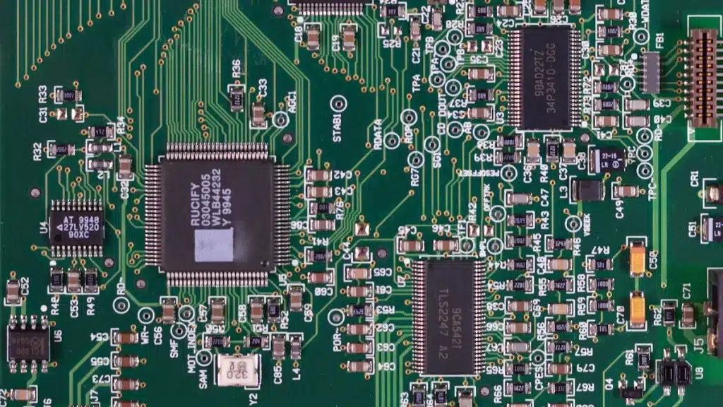
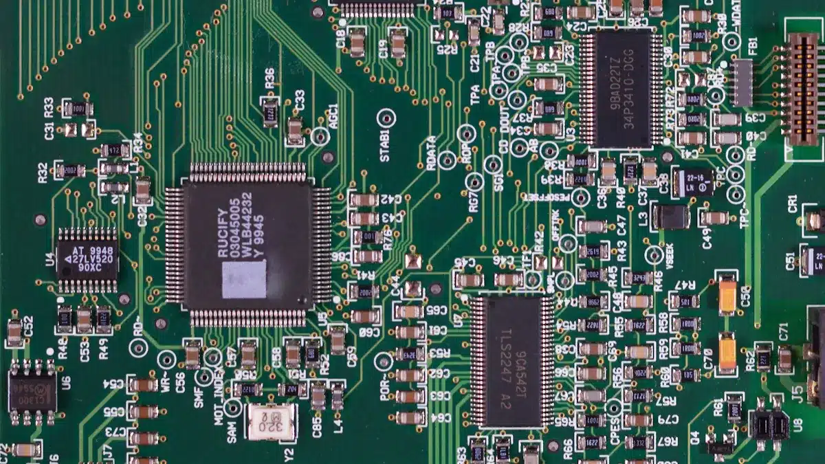
Identifying printed circuit board components on a printed circuit board is very important. It helps with fixing problems and designing better devices. Common printed circuit board components include resistors, capacitors, transistors, and diodes. Each printed circuit board component has an important job in how electronic devices work. Learning to recognize these printed circuit board components will improve your electronics skills.
Key Takeaways
Knowing PCB parts like resistors, capacitors, and transistors is important for fixing and making electronic devices. – Use reference designators and labels on parts to find them correctly. For example, ‘R’ means resistor and ‘C’ means capacitor. – Use tools like magnifying glasses and multimeters to help find parts, especially on busy PCBs.
PCB Component Types
When you work with printed circuit board components, you will see two main types: passive and active components. Knowing the difference between these two groups is important for fixing problems and designing.
Passive Components
Passive components do not need an outside power source to work. They change electrical signals by storing, using, or filtering energy. Common examples are:
Resistors: Control current flow, stop overload, and help with voltage division.
Capacitors: Store and release electrical energy, filter noise, and keep voltage steady.
Inductors: Store energy in a magnetic field and help with filtering.
Here’s a quick overview of their functions:
Component | Function |
|---|---|
Resistors | Control current flow, stop overload, and help with voltage division. |
Capacitors | Store and release electrical energy, filter noise, and keep voltage steady. |
Inductors | Store energy in a magnetic field, help with filtering noise and energy storage. |
Active Components
Active components, however, need an outside power source to work. They can make signals stronger and control current flow. Some common active components are:
Transistors: Work as amplifiers or switches, important for digital and analog circuits.
Diodes: Let current flow in one direction, used in changing and controlling voltage.
Integrated Circuits (ICs): Small circuits that improve performance and lower power use.
Integrated circuits are often the main parts of PCBs. They have many transistors and other components, allowing complex tasks like amplification and signal processing.
By recognizing these printed circuit board components, you can understand how electronic devices work and fix problems better.
Methods for Identifying Components
Finding components on printed circuit boards needs careful looking and the right tools. You can get better at identifying them by using two main methods: reading markings and using special tools.
Reading Markings
Markings on components give important information for identification. Each component usually has letters and numbers that show its type and details. Here are some key points to remember:
Reference Designators: These codes help you find components on the PCB. For example, “R” means a resistor, and “C” means a capacitor. The table below shows common reference designators:
Component | |
|---|---|
A | Sub-assembly |
C | Capacitor |
D | Diode |
F | Fuse |
Q | Transistor |
R | Resistor |
U | Integrated circuit |
Z | Zener diode |
Component Markings: Many components have markings that show their values or part numbers. For example, resistors use color bands to show resistance. Capacitors may have numbers or printed values for capacitance. Knowing these markings is key for correct identification.
Tip: Always check the manufacturer’s datasheet for detailed information about the component’s specifications and markings.
Using Tools
Besides reading markings, you can use different tools to help identify components, especially on crowded PCBs. Here are some useful tools:
Magnifying Glasses and Digital Microscopes: These tools help you read small markings better. Good lighting can also help remove shadows that hide details.
Multimeters: These devices measure electrical properties like resistance and capacitance. They can help you find broken components by testing how they work.
Thermal Cameras: These cameras find temperature changes on the PCB. They can spot overheating components, which may mean something is wrong. This is especially helpful for finding short circuits caused by too much current.
Reference Sources: Use SMD codebooks and online resources to decode part markings. These references turn codes into their values and specifications.
By mixing your knowledge of markings with the right tools, you can find printed circuit board components and fix problems more easily.
Visual Recognition Techniques for PCB Components
Seeing printed circuit board components can really help you fix problems. You can quickly spot components by looking at their shape, size, and how they are arranged on the PCB.
Shape and Size
The shape and size of components give important hints for identifying them. Each type of component has a usual shape and size that you can learn. For example, resistors are often cylindrical, while capacitors can be cylindrical or rectangular.
Here’s a table showing the common shapes and sizes of PCB components:
Component Type | Package Size | Dimensions (mm) |
|---|---|---|
Capacitors | 0201 | 0.6 x 0.3 |
1206 | 3.2 x 1.6 | |
Resistors | 0201 | 0.6 x 0.3 |
1206 | 3.2 x 1.6 | |
Diodes | SOT-23 | 2.9 x 2.4 |
SOT-223 | 6.7 x 3.7 | |
Transistors | SOT-23 | 2.9 x 2.4 |
SOT-223 | 6.7 x 3.7 |
By getting to know these sizes, you can easily find components on a PCB.
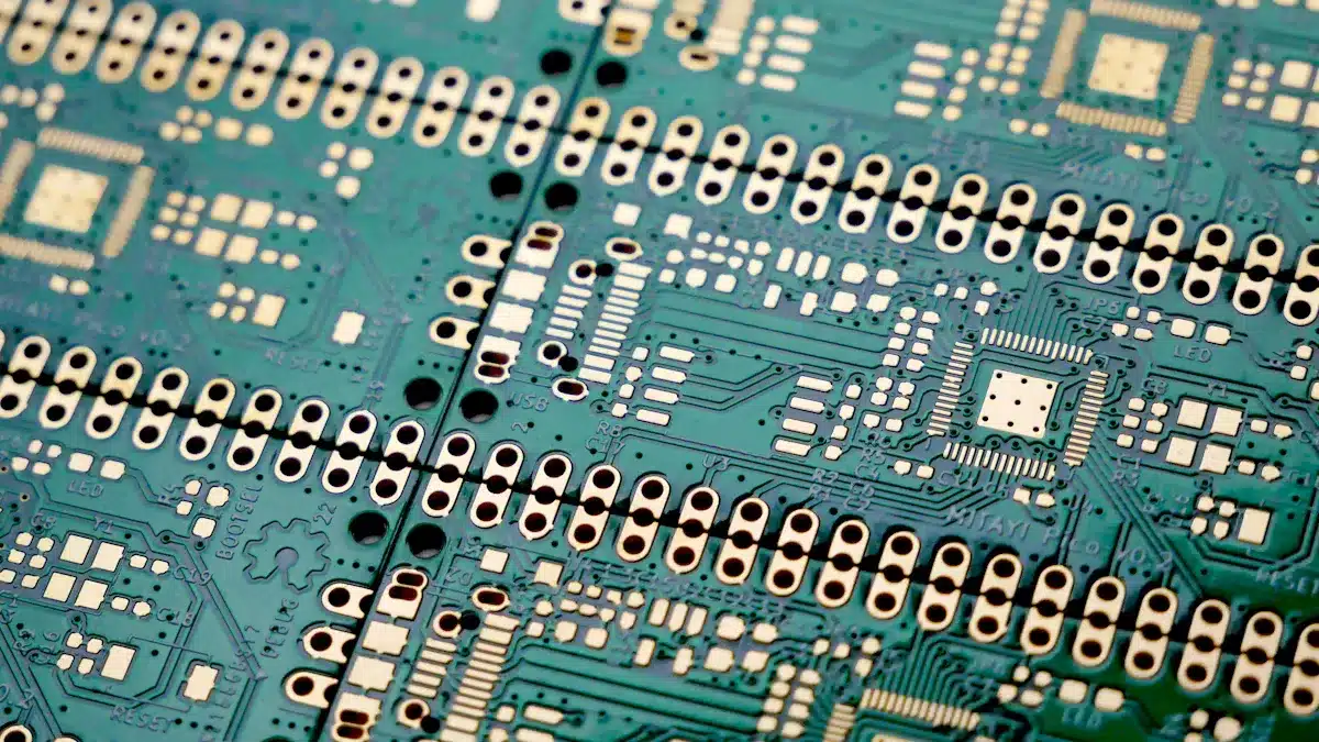
Layout Patterns
How components are laid out on a PCB is also very important for identification. You can often tell what type of component it is by where it is placed and how it is arranged. For example, through-hole components have leads that go through the board, while surface-mount devices (SMDs) sit flat on top.
Here’s a comparison of the visual differences between through-hole and surface-mount layouts:
Feature | Through-Hole Layout | Surface-Mount Layout |
|---|---|---|
Component Attachment | Components go into holes in the board | Components stick to the surface |
Lead Length | Longer leads for going through | Shorter leads, no need to go through |
Density | Fewer components close together | More components close together |
Assembly Method | Usually hand-soldered | Often put together by machines |
Space Utilization | Needs more space because of lead holes | More compact, uses both sides of PCB |
Ease of Assembly | Easier for hobbyists because of space | Needs precision but fits more components |
Right now, over 90% of PCB assemblies use surface-mount components. This shows a big change in how electronics are made.
Using visual recognition techniques can make fixing PCBs faster and more accurate. For example, computer vision systems can scan a PCB in seconds and find tiny defects. These systems can detect problems with over 95% accuracy, making sure even small issues are found quickly.
By learning these visual recognition techniques, you can get better at spotting printed circuit board components. This will help you troubleshoot and design better.
In this blog, you learned important ways to recognize components on PCBs. You looked at methods like reading markings, using tools, and visual recognition techniques.
To get better at this, try these strategies:
Visual Inspection: Use magnifying tools and good lighting.
Understanding Reference Designators: Get to know the alphanumeric codes.
Using Circuit Schematics: Read schematics to see how components connect.
Markings and Labeling: Notice the printed markings carefully.
Practice these techniques often. They will help you identify components better.
FAQ
What are the most common components on a PCB?
You will usually see resistors, capacitors, diodes, and transistors on a PCB. Each one is very important for how the circuit works.
How can I identify surface-mount components?
Check for their flat shape and small size. Use a magnifying glass to read the markings better.
Why is it important to read component markings?
Reading markings helps you know the values and details of components. This information is useful for fixing problems and repairs.
See Also
Innovative Approaches to PCBA Testing in Electronics Production
Proven Strategies for Performing PCBA Failure Investigations
Uncovering Key Distinctions Between PCBA and PCB Technologies