Choosing the right circuit board material is important. It can change how well a device works. It also affects how long the device will last. Each pcb has special features. These features affect how electricity moves, how it handles heat, and how much it costs. Researchers found that the surface of a pcb matters. It can change how often it might break. This is true when there is a lot of moisture or dirt. So, picking the right printed circuit board material is important. It helps the board work better and last longer. Engineers and designers study each circuit board material. They want to find the best one for their projects.
Key Takeaways
Picking the right circuit board material changes how a device works. It also changes how it handles heat, signal strength, and price.
FR-4 is the most used and cheapest material. It works well for many devices. But it is not great for very fast signals or high heat.
Special materials like PTFE and ceramic give clearer signals and handle heat better. But they cost more and need careful planning.
Metal core and ceramic boards move heat away very well. They are best for power electronics, cars, and planes.
Flexible PCBs can bend to fit small spaces. They are good for wearables and medical tools. But they may not work for big or strong devices.
Key Circuit Board Material Types
FR-4 and FR408HR
FR-4 is the most used circuit board material. It has glass and epoxy, which makes it strong and hard to burn. FR-4 gives good strength and keeps electricity safe. Many electronics and machines use FR-4. FR408HR is a better type of FR-4. It can handle more heat and is even stronger. FR408HR is used in fast communication, cars, planes, and medical tools. Both types work well, but FR408HR is best for tough jobs that need to stay cool and keep signals clear.
Property Type | FR-4 (via FR408) | FR408HR |
|---|---|---|
Electrical | Dielectric constant (Dk): 3.67 | Dielectric constant (Dk): 3.68 |
Dissipation factor (Df): 0.0120 | Dissipation factor (Df): 0.0092 | |
Thermal | Glass transition temperature (Tg): 180°C | Glass transition temperature (Tg): 190°C |
Decomposition temperature (Td): 360°C | Decomposition temperature (Td): 360°C | |
Mechanical | Reliable and durable | Higher flexural and tensile strength |
CEM-1 and CEM-3
CEM-1 and CEM-3 are cheap copper boards. CEM-1 uses paper, so it costs less. It only works for one-sided PCBs. CEM-1 is not very strong and does not handle heat well. CEM-3 uses glass and epoxy, so it is stronger and safer from fire. CEM-3 can be used for two-sided PCBs and some with more layers. Many simple electronics and LED lights use CEM-3. FR-4 is stronger and lasts longer, but CEM-1 and CEM-3 are good for easy, low-cost jobs.
PTFE (Teflon)
PTFE is a special board material. It has a low dielectric constant and very low dissipation factor. PTFE is used for high-frequency and microwave circuits. It lets signals move faster and lose less energy than FR4. PTFE’s dielectric constant is between 2.1 and 2.5. Its dissipation factor is about 0.001. PTFE is used in RF, satellites, and radar. PTFE costs more than FR4, but it is needed for circuits that must keep signals strong.
Property | Value Range | Significance in High-Frequency PCB Applications |
|---|---|---|
Dielectric Constant (Dk) | 2.1 to 2.5 | Higher signal speed and better integrity compared to FR4 (~4.5) |
Dissipation Factor (Df) | ~0.001 or lower | Reduces signal loss and distortion, critical for RF and microwave |
Metal Core
Metal core boards use aluminum or copper as a base. These boards move heat away from parts better than FR4. Metal core PCBs do not need thermal vias because the metal moves heat. They are used in LED lights, power electronics, cars, and planes. Metal core PCBs are strong and last long. They are good for places with lots of power and heat.
Metal core PCBs have special materials that help move heat.
Their thermal conductivity is 1.0 to 4.0 W/mK, much more than FR4.
They are used in LED lights, power supplies, and car lights.
Ceramic
Ceramic boards are very strong and can take high heat. Ceramic PCBs work from 350°C to over 800°C. They do not break from shaking, hitting, rust, or water. Many power electronics, LED lights, cars, planes, and medical tools use ceramic PCBs. Ceramic boards can hold more parts and move heat better than FR4. But ceramic PCBs can break easier and cannot be made very big.
Ceramic PCBs help make small circuits and better paths.
They are used in solar panels, wireless charging, and strong LEDs.
Flexible Substrates
Flexible boards use polyimide or other bendy stuff. These boards can bend and twist to fit tight spaces. Polyimide is the most used because it is strong and bends well. Flexible PCBs are found in phones, wearables, medical tools, and car dashboards. Thin copper makes them bend more. Thick copper makes them stiffer. Flexible PCBs cost less to put together and help make new designs.
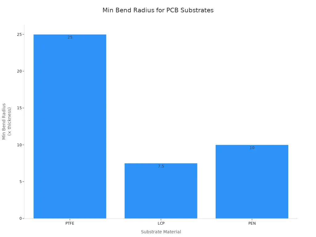
Tip: Flexible PCBs work best when designers use no glue and move traces around to make them bend easier and last longer.
Printed Circuit Board Material Properties
Knowing about pcb material properties helps engineers pick the best board. These properties change how signals move, how strong the board is, and how much it costs. The next parts talk about how electrical, thermal, and mechanical properties affect how a pcb works.
Electrical Properties (Dk, Df, Dielectric Strength)
Electrical properties are important for keeping signals clear. Dielectric constant (Dk) shows how well a material holds electric energy. Dissipation factor (Df) tells how much energy turns into heat. Dielectric strength means how much voltage a material can take before it breaks. These things help keep signals strong, especially in fast or high-frequency circuits.
Material Type | Dielectric Constant (Dk) Range | Dissipation Factor (Df) Range | Notes |
|---|---|---|---|
FR-4 | Common pcb material, moderate Dk and higher Df | ||
Rogers (Ceramic-filled PTFE) | 2.2 to 10.2 (varies) | 0.001 to 0.004 | Low Df, stable Dk, good for RF/microwave |
PTFE (pure) | Near 0.001 | Very stable, ideal for high-frequency |
PTFE is special because it has low Dk and Df. This helps keep signals strong in RF and microwave circuits. FR-4 has higher Dk and Df, so it is not as good for fast signals. But it still works well for most pcb jobs.
Note: People use tests like electrical testing, E-test, and in-circuit testing. These tests check these properties and make sure signals stay strong.
Thermal Properties (Thermal Conductivity, TG)
Thermal properties help control heat and keep the board working well. Thermal conductivity shows how fast heat moves away from hot parts. Glass transition temperature (TG) is when the material gets soft. If a pcb gets hotter than its TG, it can bend or stop working right.
Material | Thermal Conductivity (W/mK) | Glass Transition Temperature (TG) |
|---|---|---|
0.3 – 0.35 | >150°C | |
Standard FR4 | ~0.3 | ~130°C |
High-Tg FR4 | N/A | |
Aluminum | 200 – 250 | N/A |
Ceramic | 20 – 70 | N/A |
PTFE | 0.3 – 0.4 | N/A |
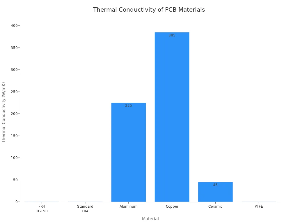
High-Tg FR-4 and ceramic boards keep their shape at high heat. Good heat control helps keep signals clear and stops damage.
Mechanical Strength and Durability
Mechanical strength and durability help the pcb last longer. Strong boards do not bend, crack, or warp easily. FR-4 is stiff and strong, so many people use it. Flexible substrates, like polyimide, can bend and fit in small spaces. CEM-3 is strong but not as much as FR-4.
Substrate Material | Flexural Strength (MPa) | Flexural Modulus (GPa) | Description |
|---|---|---|---|
FR-4 | 17-20 | High mechanical strength and stiffness | |
CEM-3 | N/A | N/A | Good strength and rigidity |
Flexible Substrates | N/A | N/A | Flexible, thin, used for bendable applications |
Durability also means the board can handle heat, water, and chemicals. High-Tg and ceramic boards last longer in tough places. Good design and the right material help keep signals strong and make the pcb last longer.
PCB Material Comparison Chart
A pcb material comparison chart helps people pick the right board. This chart lists the main features of each type. It also shows how each material changes signal quality, price, and how well it works. The chart uses tables and bullet points to make things clear.
Electrical and Thermal Performance
Electrical and thermal features change how a pcb works in different places. The chart below lists important features for fr4, ptfe, metal core, and ceramic boards. These features are dielectric constant, dissipation factor, breakdown voltage, glass transition temperature, and thermal conductivity. Each one helps with signal quality and heat control.
PCB Material | Dielectric Constant (Dk) | Dissipation Factor (Df) | Breakdown Voltage (kV/mm) | Glass Transition Temp (Tg) | Thermal Conductivity (W/m·K) | Coefficient of Thermal Expansion (CTE, ppm/°C) | Typical Use Cases |
|---|---|---|---|---|---|---|---|
FR-4 | ~4.5 | Moderate | ≥20 | ~130°C | ~0.3 | <50 | Consumer electronics, computers |
PTFE | ~2.2 (low) | <0.005 (low) | N/A | N/A | N/A | N/A | RF, microwave, satellites |
Metal Core | N/A | N/A | N/A | N/A | Up to 10 | N/A | LED lighting, power modules |
Ceramic | N/A | N/A | Up to 50 | N/A | N/A | ~6 (IC substrate grade) | High-voltage, automotive, medical |
fr4 has okay electrical features and low heat movement. It works for most pcb jobs.
ptfe has low dielectric constant and dissipation factor. This keeps signals strong in fast circuits.
Metal core boards move heat away from parts very fast.
Ceramic boards can take high voltage and do not expand much. They are good for tough and high-voltage jobs.
Note: Picking the right material from the chart can help keep signals clear and stop overheating.
Cost and Manufacturability
The price and how easy a pcb is to make depend on the material. The chart below compares old materials like cem-1, cem-3, and flexible boards with special ones like ptfe and ceramic. It looks at base material, price, how they are made, strength, bending, how many are made, and design choices.
Aspect | Traditional Materials (CEM-1, CEM-3, Flexible Substrates) | High-Performance Materials (PTFE, Ceramic) |
|---|---|---|
Base Material | Composite epoxy with paper and glass fiber (cem-1, cem-3); polyimide for flexible | High-purity ceramic powders; ptfe often reinforced with fillers |
Cost | Low cost due to inexpensive raw materials and mature mass production | 5-20 times higher cost due to expensive raw materials and complex processes |
Manufacturing | Well-established, energy-efficient, high-volume production with high yields | Complex, energy-intensive (high-temperature firing for ceramics), lower yields |
Mechanical Properties | Reasonable mechanical strength; flexible substrates use polyimide for flexibility | Superior thermal, electrical, and environmental properties; ceramics are brittle and rigid |
Suitability for Flexibility | Flexible substrates suitable for flexible circuits | Ceramics are brittle and unsuitable for flexible or rigid-flex applications |
Production Volume | High volume with economies of scale | Typically lower volume, less automation |
Design Considerations | Greater design freedom, finer trace/space capabilities | More constraints, coarser features, specialized design needed |
cem-1 and cem-3 are cheap and easy to make. They are good for simple and big pcb jobs.
Flexible boards use polyimide. They let you make cool shapes and fit in small spots.
ptfe and ceramic cost a lot more. They need special ways to make them and fewer are made.
Special materials give better signal and last longer. They are best when you need top quality and can pay more.
Tip: Use the chart to find the best mix of price and features for your project. Special materials work better but cost more.
The chart helps people see the differences in features, price, and how they are made. This makes it easier to choose the best pcb for each job. Always check the chart before you start a new design.
Choosing the Right PCB Material
Application-Based Recommendations
Picking the best PCB material depends on what the project needs. Engineers look at how fast signals must go, how hot things get, and how long the board should last. The material comparison chart helps them see which materials work for different jobs.
FR-4 is good for things like phones and computers. It is cheap and works well for most jobs that do not need super fast signals. Many home devices use FR-4. If a device gets hot, like power supplies or LED lights, aluminum PCBs are better. These boards move heat away fast. This keeps the device safe and working longer.
For things like 5G phones, Wi-Fi routers, and radar, engineers need materials with low dielectric constant and low dissipation factor. PTFE-based laminates, like Rogers or Taconic, are used for these high-speed jobs. These materials keep signals strong and clear, even when they move very fast. The pcb material comparison chart shows PTFE and ceramic-based materials are best for high-frequency and tough places. Ceramic PCBs also move heat well and stay stable. This makes them good for cars, planes, and medical tools where safety matters.
Cars and planes face heat, shaking, and wet air. Engineers pick ceramic or metal core PCBs for these jobs. These boards can handle lots of power and tough spots. Polyimide is also good for flexible circuits in cars and planes. It stays strong when bent or heated.
When engineers use the material comparison chart, they check important things for high-frequency or high-power jobs:
Electrical properties: dielectric constant (Dk), loss tangent (Df), and controlled impedance for signal strength.
Thermal properties: thermal conductivity, thermal stability, and coefficient of thermal expansion (CTE) for heat control.
Environmental factors: resistance to temperature changes, water, and stress.
Cost-performance trade-offs: balancing price with what the board needs to do.
Manufacturability: how easy it is to make the board, including via design and process fit.
The pcb material comparison chart also shows FR-4 is good for medium frequency and when you need to save money. But it does not work well for very fast signals. PTFE and ceramic are better for advanced jobs, but they cost more.
Tip: Always pick the PCB material that fits the job. Use the material comparison chart to compare features and make the best choice.
Balancing Performance and Cost
Engineers must think about both performance and cost when picking a pcb material. The material comparison chart helps them see the differences between regular and special materials for fast jobs.
Material Type | Cost | Performance Characteristics | Advantages | Limitations |
|---|---|---|---|---|
FR4 (Standard) | Low | Good electrical insulation, moderate dielectric constant | Cost-effective, versatile, easy to manufacture | Limited high-frequency performance, absorbs water |
Advanced High-Frequency Dielectric Materials | High | Low dielectric constant, low dissipation factor, high stability | Superior signal integrity, thermal stability | Higher cost, complex fabrication |
The chart shows FR-4 is a good pick for most jobs. It is cheap and easy to use. But it does not work well for very fast signals or hot places. Special materials like PTFE and ceramic are better for fast signals and heat. But they cost more and are harder to make.
To save money, engineers sometimes use hybrid designs. They put special materials only where fast signals go. They use FR-4 for other layers, like power and ground. This keeps costs low and still gives good performance. The material comparison chart helps spot where special materials are needed and where FR-4 will work.
For test boards, engineers usually pick FR-4. This saves money and lets them test ideas fast. For big production, they may switch to special materials if the job needs better performance or longer life.
Here is a simple checklist for picking the right pcb material:
List what the job needs: speed, power, place, and safety.
Check the pcb material comparison chart for electrical and heat features.
Compare cost and performance for each material.
See if hybrid boards can save money and still work well.
Make sure the material fits the way the board is made.
Note: Using the material comparison chart and this checklist helps engineers make smart choices for any job.
The material used for a circuit board changes how a device works and lasts. Each material has special strengths for certain jobs, like handling heat, keeping signals clear, or saving money. Engineers use a guide to help pick the best material for each job. They think about heat, electricity, and how much money they can spend. FR-4 is good for many uses. Aluminum PCBs are better when things get hot. Fast circuits need special materials. Picking the right material helps devices work well and last longer. The best material keeps electronics safe, strong, and working for a long time.
FAQ
What is the most common material for circuit boards?
FR-4 is used in most circuit boards. It is made from glass and epoxy. FR-4 is strong and safe to use. It does not cost a lot of money. Many computers and phones have FR-4 boards.
Why do engineers choose PTFE for high-frequency circuits?
PTFE has a low dielectric constant and low loss. This helps signals stay clear and move fast. Engineers use PTFE in radios, satellites, and 5G devices.
Can flexible PCBs replace regular rigid boards?
Flexible PCBs can bend and fit in small spaces. They are good for wearables and medical tools. But they do not always work for big or strong devices.
How does the choice of PCB material affect cost?
Special materials like PTFE and ceramic cost more than FR-4 or CEM-1. These materials cost more because they work better and are harder to make. Engineers try to balance price and what the project needs.
See Also
Understanding How PCBA And PCB Differ In Function And Design
Unveiling The Key Distinctions Between PCBA And PCB
Essential Contrasts Of PCB And PCBA In Electronics Production