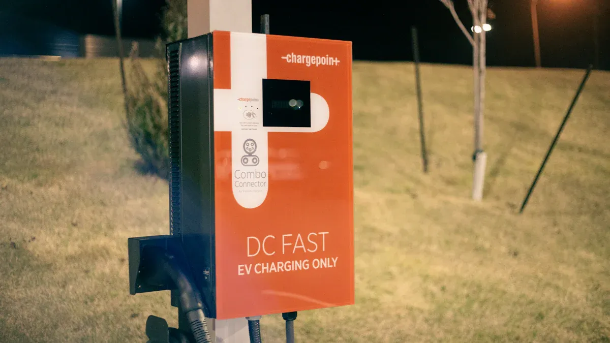
Fast charging station PCB assembly is crucial for charging electric cars. Utilizing relays on fast charging station PCBs simplifies the design and reduces costs. This modification enhances the system’s performance and reliability. Tests such as heat and function checks ensure the system remains safe and operates effectively. Addressing overheating issues and incorporating safety features like voltage control protect users. These enhancements contribute to making fast charging stations safer and more durable, while also advancing electric car charging technology.
Key Takeaways
Think about high power and voltage needs when making PCBs for fast chargers. Use thicker copper and strong materials to make them safer and work better.
Keep the system cool with smart heat control methods. Add copper-graphene layers and cooling systems to stop overheating and make chargers last longer.
Follow safety rules to protect users. Use tools to check insulation and stop electrical noise for safe and steady charging.
Pick good parts for power supplies and connectors. Use connectors that are easy to fix and work well with high currents.
Test everything carefully to make sure it works. Do tests to check how it functions and meet safety rules to keep EV chargers safe and reliable.
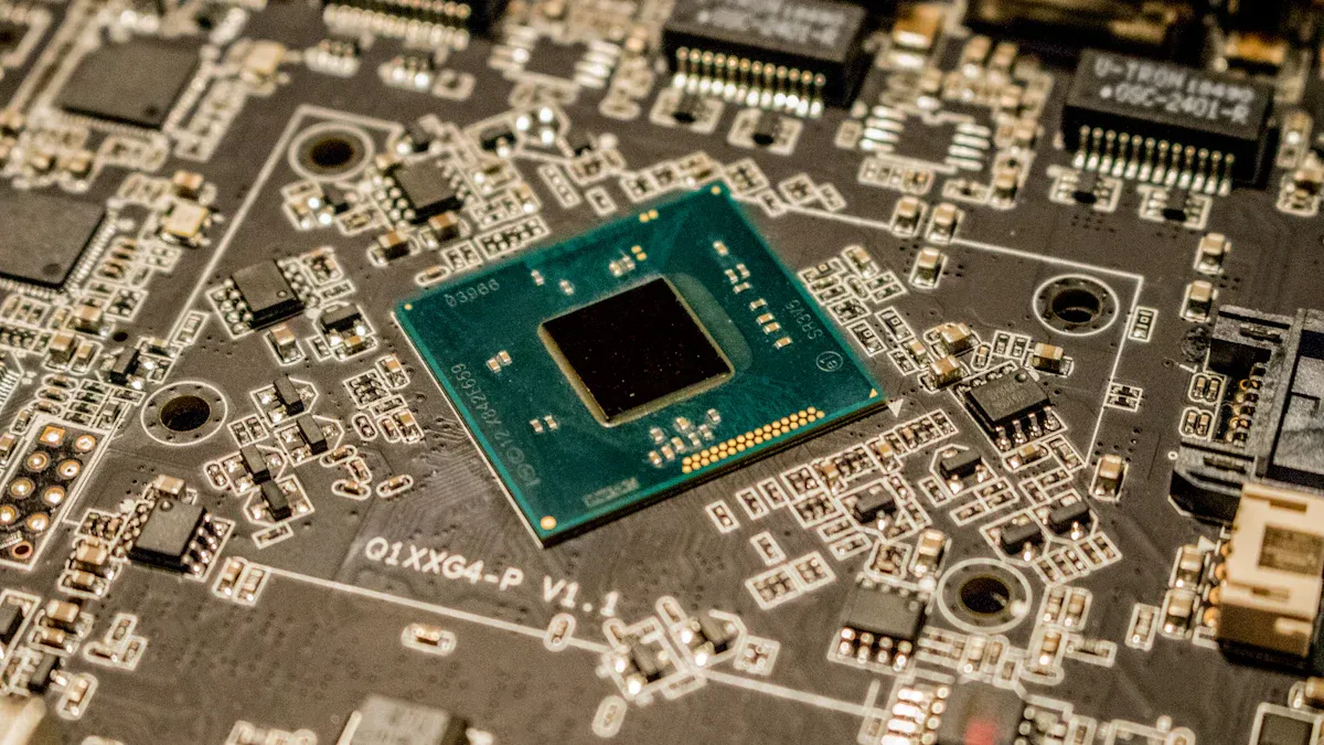
Design Considerations for Fast Charging Station PCB Assembly
Power and Voltage Requirements
When making PCBs for fast chargers, plan for high currents. These systems need strong circuits to move energy efficiently. Using thicker copper on the PCB helps carry more current. It also spreads heat better, cutting energy waste and improving charging. Picking materials like high-CTI substrates makes them work well with high voltage. Adding extra insulation keeps users safe and avoids electrical problems.
To make everything work smoothly, match power circuits to energy needs. Good voltage control keeps the system steady and prevents overloads. This setup makes the system reliable and works with many car charger designs.
Thermal Management for Long-Term Reliability
Good heat control is key to keeping chargers working well. Too much heat can break parts and shorten the system’s life. Using copper-graphene layers in the PCB helps spread heat faster. This keeps parts cool during heavy charging times.
You can also use advanced cooling, like liquid cooling with special materials. These methods keep temperatures steady across the system. Tools like heat simulation software help place parts and manage heat better. This planning ensures the system lasts long and works efficiently.
Meeting Safety and Industry Standards
Safety is very important when designing PCBs for fast chargers. Follow rules like IEC 60664-1 to ensure strong insulation. High-CTI materials and coatings keep insulation strong in tough conditions. These steps protect people and equipment from electrical dangers.
Using monitoring tools like IMDs adds extra safety. These tools find leaks and activate protection quickly. Adding EMC suppression technology ensures the system meets safety standards. By doing this, you create chargers that are safe, efficient, and reliable.
Component Selection for Electric Vehicle Charging PCBs
Reliable Power Supplies and Connectors
Choosing good power supplies and connectors is very important. They must handle high currents without overheating or wasting energy. Pick power supplies with steady output and low ripple for smooth charging. Use strong connectors with low resistance to transfer energy better and avoid heat.
For fast chargers, modular connectors are a smart option. They are easy to replace and fix, saving time. Gold-plated contacts last longer and resist rust, making them reliable. By using strong power supplies and connectors, charging circuits work better.
Safety Components for Circuit Protection
Protecting circuits is key when designing EV charger PCBs. Without protection, circuits can break from overloads or short circuits. Add fuses, circuit breakers, and surge protectors to keep the system safe. These parts stop electricity flow during problems to prevent damage.
Thermal devices, like thermistors, check and control heat levels. They stop parts from getting too hot. Insulation monitoring devices (IMDs) find leaks and improve safety by acting quickly. With these safety tools, charging circuits stay safe and dependable.
Strong Materials for Better Performance
The materials in your PCB affect how well it works and lasts. High-CTI substrates, like Rogers RO4835, offer great insulation and handle high voltages. These materials meet safety rules and work reliably.
Coatings, like polyurethane or silicone, shield the PCB from water, dust, and heat. They keep insulation strong even in tough conditions. For heat control, copper-graphene layers spread heat well, keeping the system cool. Picking the right materials makes EV charging PCBs last longer and work better.
Step-by-Step PCB Assembly Process
Preparing and Aligning PCB Components
The first step is getting the parts ready and lined up. Check that all parts match the design plan. Use a list, called a BOM, to confirm the type and number of parts. This helps avoid mistakes and keeps the charger working well.
Clean the PCB to remove dust and dirt. A clean board helps the solder stick better and improves assembly. Work on an anti-static table to protect delicate parts from damage.
Place the parts carefully by following the PCB design map. Machines can place parts quickly and accurately, reducing mistakes. For hand assembly, use tools like tweezers to position parts correctly. Proper placement is key to making chargers reliable.
Soldering Techniques and Material Quality
Soldering connects parts to the board so electricity can flow. Use good solder materials, like lead-free ones, for strong and safe connections. These materials are durable and meet environmental rules.
There are two main soldering methods: wave soldering and reflow soldering. Wave soldering works for parts with pins, while reflow soldering is for flat parts. Both methods make strong connections for efficient charging.
Keep the right temperature when soldering. Too much heat can break parts, and too little heat makes weak joints. Use soldering tools with exact temperature controls for the best results. Check solder joints for problems like cracks or extra solder. Good soldering keeps chargers working for a long time.
Quality Control and Automation in Assembly
Quality checks are very important in PCB assembly. They make sure the final product is safe and works well. Start by looking for obvious issues, like misplaced parts or bad soldering.
Machines with cameras, called AOI systems, can find tiny errors people might miss. These machines check if every part is in the right spot and soldered well. For deeper checks, X-ray machines can find hidden problems in layered boards.
Test the PCB by simulating real-life use to ensure it works properly. Automation helps speed up testing and makes it more accurate. Using automated tools improves the quality and reliability of PCBs for EV chargers.
Testing and Validation for EV Charger PCBs
Functional Testing for Performance Assurance
Functional testing checks if the EV charger PCB works well. Simulate charging to test energy transfer and charging speed. Use tools like load simulators to check power handling.
Run continuous charging cycles to find weak spots in circuits. This helps improve long-term performance and reliability. Ground current detection systems monitor electricity flow. They stop problems by catching issues early.
Test communication between the charger and the car. Make sure the PCB works with different EV models. Functional tests improve the efficiency and dependability of charging stations.
Safety Compliance and Certification
Safety rules are important for EV charger PCBs. Follow industry standards to keep chargers safe and reliable. Certifications like IEC 61851 prove the PCB meets safety rules. UL certifications confirm it works with safety protocols.
Lithium batteries need UN38.3 testing for safe transport. This includes checks for electrical, mechanical, and environmental safety. Tests like vibration and shock prevent overheating risks.
Certification Requirement | Description |
|---|---|
UN38.3 Testing | Ensures lithium batteries are safe for transport. Covers electrical, mechanical, and environmental safety. |
Extensive Testing | Includes vibration, shock, short circuit, and overcharge checks to avoid overheating. |
Design Changes | Any updates need recertification to meet safety rules. |
If you change the PCB design, get it recertified. This keeps it aligned with safety standards. Certifications make chargers safer and more reliable.
Environmental and Stress Testing Procedures
Environmental testing checks how the PCB handles tough conditions. Test it in high heat, humidity, and mechanical stress. This ensures it works well in harsh environments.
Simulate real-world problems like power surges or system failures. Find weak points and improve safety features. Use thermal chambers to test heat resistance. Vibration tables check if it stays stable under movement.
Stress testing also looks at long-term use. Run the PCB through many charging cycles to check wear. This ensures it stays fast and safe over time. Environmental and stress tests help create reliable charging stations.
Ensuring Efficiency and Reliability in PCB Assembly
Optimizing PCB Layout for Performance
A good PCB layout helps improve charging performance. Keep high-current paths short to reduce energy loss. Shorter paths lower resistance and make the system more efficient. Place power parts close together to save energy and boost reliability.
Put heat-making parts near cooling areas to manage heat better. This setup stops overheating and keeps charging speeds steady. Use simulation tools to test your design before building it. These tools find weak spots and help improve the layout for better results.
Advanced Materials and Modular Designs
Using better materials can make your PCB work more efficiently. High-CTI substrates, like Rogers RO4835, offer strong insulation and handle high voltages. These materials stay safe and last long, even in tough conditions. Add coatings, like silicone or polyurethane, to protect against water and dust.
Modular designs make fixing problems easier. You can swap out broken parts without taking apart the whole system. This saves time and keeps charging stations running longer. Modular designs also let you upgrade for new charging technologies in the future.
Strategies for Long-Term Reliability and Maintenance
To keep your system reliable, focus on design and testing. Pick parts that are known to last a long time. Use materials that don’t wear out easily, like low-water-absorption substrates. These materials work well even in bad weather.
Regular check-ups are important to keep chargers working. Plan inspections to find worn-out parts. Replace broken pieces quickly to avoid bigger problems. Use monitoring tools, like insulation monitors, to catch issues early. These tools make the system safer and more dependable.
Building PCBs for EV fast chargers needs careful planning and testing. Each step helps the system work safely and efficiently. By focusing on these tasks, you can make chargers that follow rules and work well.
Good PCB assembly is key to improving EV charging systems. It allows faster charging, saves energy, and keeps users safe.
Using smart assembly and testing methods makes chargers reliable. It also encourages new ideas. This helps create a safer and greener future for electric cars.
FAQ
What does PCB assembly do in EV fast chargers?
PCB assembly helps transfer energy safely and reliably. It connects parts like power supplies, connectors, and safety tools. This makes the charger work smoothly and last longer.
How does heat control make PCBs better?
Heat control stops parts from getting too hot. Materials like copper-graphene layers spread heat well. Cooling systems keep parts cool, making the PCB last longer and charge efficiently.
Can EV stations use wireless charging?
Yes, EV stations can have wireless charging. It removes the need for plugs, making it easier to use. It also reduces wear on parts but needs special PCB designs for high-frequency energy.
What are the best materials for EV charger PCBs?
Strong materials like Rogers RO4835 and silicone coatings work well. They insulate, last long, and resist water and heat. These materials keep the PCB safe and durable.
Why is following safety rules important for PCBs?
Safety rules keep chargers safe for people and equipment. Certifications like IEC 61851 prove the PCB works safely. They lower risks like overheating or electrical problems.
See Also
Essential Strategies to Enhance PCB Assembly Productivity
10 Professional Insights for Cost-Effective PCBA Production
A Comprehensive Guide to PCBA Manufacturing Techniques