
Testing and checking PCBs are very important for Industrial IoT PCB testing and validation. PCBs are the main part of electronics used in factories, robots, and control systems. Good PCBs make these systems work better and safer, helping keep work running smoothly.
More PCB testing is needed as new tech is used in factories.
Good PCBs help machines work well where accuracy and time matter.
Testing finds problems early, stopping expensive breakdowns later.
Even though it’s important, testing PCBs for Industrial IoT PCB testing and validation has challenges. These include handling tricky designs, following rules, and keeping costs low. Solving these problems makes sure your electronics work well in tough factory settings.
Key Takeaways
Testing PCBs is important to make sure they work well. It finds issues early and stops expensive failures.
Use different testing methods like looking by hand, using machines to check, and testing circuits to check everything.
Stress testing copies real-life conditions. It checks if PCBs can handle heat, water, and shaking in factories.
Writing down and studying test results helps make better designs and follow rules.
Keep up with industry rules to gain trust and avoid problems.
Overview of Industrial IoT PCB Testing and Validation
Why PCB testing matters in Industrial IoT
Testing circuit boards is key to making electronics reliable. Industrial IoT systems work in tough places where accuracy and strength are important. Finding problems early stops costly breakdowns and delays. Testing also checks if PCBs meet the needed standards for industrial use.
Modern tools like Automated Optical Inspection (AOI) and X-ray tests help a lot. AOI finds surface problems, while X-rays spot hidden issues inside the board. These methods make sure PCBs work properly, which is very important for IoT devices in factories.
How testing and validation are different
Testing and validation do not mean the same thing. Testing looks for problems or errors in the circuit board. It uses methods like In-Circuit Testing (ICT) and Functional Testing to check connections and how the board works.
Validation makes sure the PCB matches design plans and rules. This includes stress tests, like exposing the board to heat or shaking. Testing finds quick problems, but validation checks if the board will last and follow industry rules.
Goals of testing and validation for Industrial IoT PCBs
The main goal of testing is to ensure the PCB works well. This means checking connections, signals, and parts placement. Testing helps find and fix problems before using the board.
Validation checks if the PCB can handle tough factory conditions. It also ensures the board meets special rules for industrial IoT. By doing both testing and validation, you can make sure the PCB is strong and works as it should.
Essential Ways to Test a PCB
Testing a PCB makes sure it works well and meets rules. Different methods have pros and cons, so pick the best one for your needs. Below are three main ways to test a PCB.
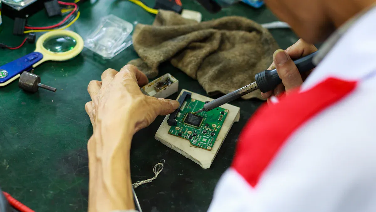
Manual Visual Inspection (MVI)
Manual Visual Inspection (MVI) is a simple way to check PCBs. You look for problems like bad soldering, wrong parts, or broken lines. It doesn’t need fancy tools, so it’s cheap for small tests.
But MVI has downsides. People can miss problems, especially on complex boards. It also takes a lot of time and isn’t good for big projects. MVI is a good start but works better with other testing methods.
Automated Optical Inspection (AOI)
Automated Optical Inspection (AOI) uses cameras and software to find defects. It’s faster and more accurate than MVI. AOI spots missing parts, wrong polarity, or solder issues. It doesn’t need the PCB to be powered during testing.
However, AOI can’t find electrical problems like short circuits. To get better results, use AOI with other tests like in-circuit testing. AOI is great for large-scale production where speed matters.
In-Circuit Testing (ICT)
In-circuit testing (ICT) checks how well a PCB works electrically. It uses probes to measure things like resistance and capacitance. ICT quickly finds issues like broken circuits or bad parts.
ICT is very reliable but needs special tools and setups. It may not catch every problem but is great for checking electrical performance. ICT is a top choice for industrial IoT PCBs.
Comparing Testing Methods
Here’s a simple table to compare these testing methods:
Testing Method | Pros | Cons |
|---|---|---|
Manual Visual Inspection | Easy and low-cost | Can miss small issues, slow for big projects |
Automated Optical Inspection (AOI) | Fast and accurate for surface problems | Can’t find electrical issues |
In-Circuit Testing (ICT) | Checks electrical performance well | Needs special tools |
By knowing these methods, you can pick the best way to test PCBs for industrial IoT.
Flying Probe Testing (FPT)
Flying Probe Testing (FPT) is a flexible way to check if a PCB works. Unlike In-Circuit Testing (ICT), it doesn’t need special tools. Instead, it uses moving probes to test the board. These probes move across the PCB, touching points to measure things like resistance and continuity.
Why Use Flying Probe Testing?
FPT is great for testing small batches or prototypes. It’s flexible because you can test new designs without extra tools. This method is also good for boards with many tiny parts.
Here are some benefits of FPT:
Saves Money: No need for expensive custom tools.
Fast Setup: Start testing quickly after programming the machine.
Very Accurate: Probes can reach tricky spots on the board.
But FPT has downsides. It’s slower than ICT for big projects. The probes also can’t handle very fast testing, which some IoT systems need.
Tip: Use FPT early in development. It helps find problems before making more boards.
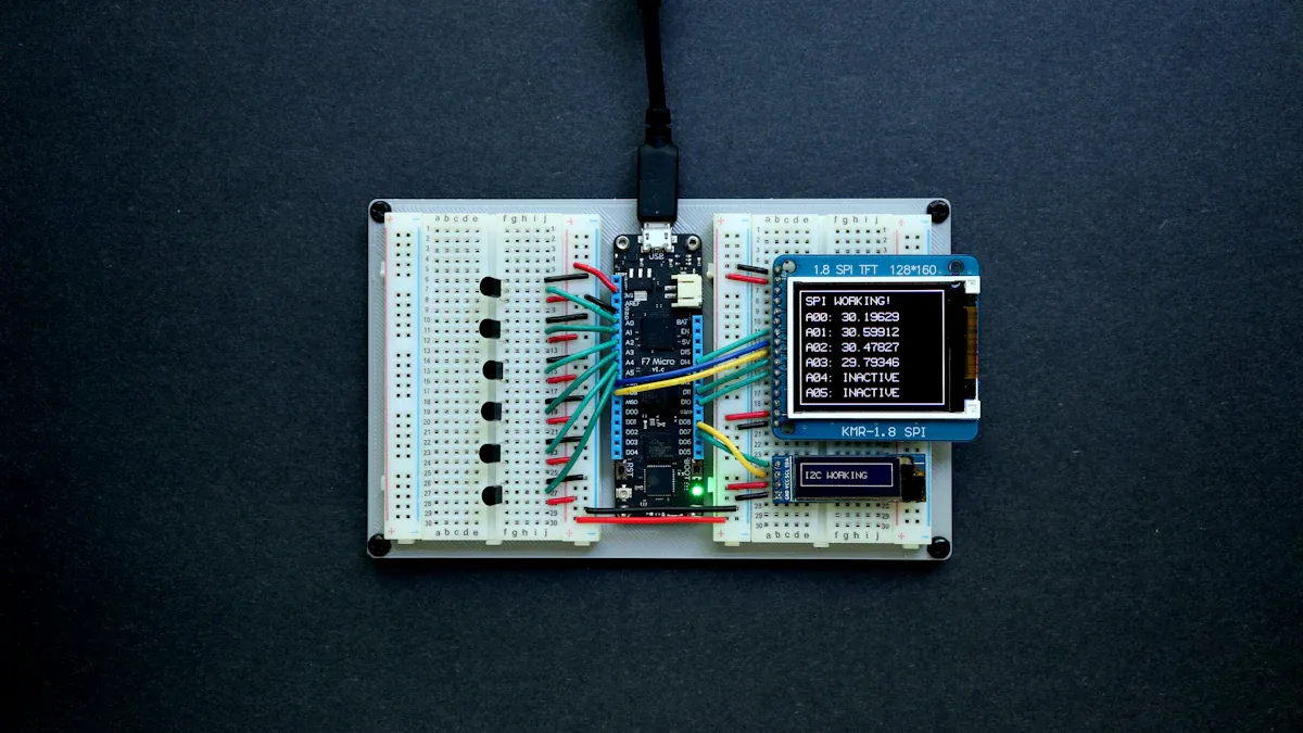
Functional Circuit Testing (FCT)
Functional Circuit Testing (FCT) checks if the PCB works in real-life conditions. It tests how the board interacts with other parts and systems.
How Does Functional Circuit Testing Work?
FCT connects the PCB to a setup that acts like its real use. For example, if the board is for an IoT sensor, the setup might include fake signals like temperature or pressure. The test checks if the board gives the right outputs.
Advantages of FCT
Real-Life Testing: Makes sure the board works as it should in its environment.
Thorough Checks: Tests both hardware and software together.
Customizable: You can adjust the test for specific needs.
FCT takes time and needs special tools. But for IoT systems, it’s important to make sure the board meets standards.
Note: Combine FCT with other tests like AOI for better results.
By learning these methods, you can choose the best way to test a PCB. Both FPT and FCT are key to making reliable boards for IoT systems.
Validation Techniques for Industrial IoT PCB Testing and Validation
Environmental stress testing (temperature, humidity, vibration)
Environmental stress testing checks if your PCB can handle tough conditions. These tests mimic real-world settings like heat, moisture, and shaking. By testing under these conditions, you can find weak spots and make the board stronger.
Temperature testing puts the PCB in hot and cold chambers. This checks if it works without breaking or overheating. Humidity testing sees how water affects the board, making sure it doesn’t rust or short out. Vibration testing shakes the board like industrial machines do. It ensures parts stay in place and connections don’t break.
These tests are very important for Industrial IoT PCB testing. They make sure your electronics work well in hard environments, lowering the chance of failure or costly repairs.
Tip: Write down all test results. This helps improve designs and quality checks.
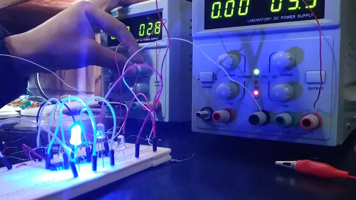
Electrical performance simulations
Electrical performance simulations test your PCB design before making it. Special software shows how the circuit works in different situations. This saves time and money by spotting problems early.
You can test things like power changes, signal issues, and power spikes. These tests check if the board works well and meets its job. For example, you can see if signals stay steady or if it handles sudden power jumps. Simulations also help arrange parts for better performance.
This is one of the smartest ways to test a PCB. It works well with other tests like in-circuit and functional testing by showing how the board acts before physical tests.
Note: Use software that fits your industry. This gives better results and smarter designs.
Compliance with industry certifications
Getting industry certifications proves your PCB is safe and high-quality. Certifications like IPC, ISO, and CE set rules for making and testing boards. They ensure your electronics follow laws and work well in factories.
To get certified, follow strict rules during design and testing. For example, you might need lab tests to check safety and environmental standards. Functional tests are key to proving the board works as planned.
Certifications show you care about quality. They build customer trust and help your product compete worldwide. By focusing on certifications, you avoid recalls, legal trouble, and bad reviews.
Reminder: Stay updated on certification rules. This keeps your PCB competitive and up-to-date.
Long-term reliability testing
Long-term reliability testing checks if your PCB works well over time. It tests how the board handles tough conditions and long use. For Industrial IoT, this is very important. Failures can stop work and cost a lot of money.
Why is long-term reliability testing important?
Industrial IoT systems run all day in hard conditions. These include high heat, shaking, and electrical noise. Over time, these can harm your PCB. Long-term testing finds weak spots before use. Fixing these early avoids problems with safety or work delays.
Tip: Long-term testing acts like years of use in less time. It shows how your PCB will work in real life.
Key methods for long-term reliability testing
There are many ways to test your PCB for long-term use. Each method checks a different part of its strength:
Thermal Cycling: Heats and cools the PCB again and again. This checks if it can handle temperature changes without breaking.
Power Cycling: Turns the PCB on and off many times. It finds problems like worn-out parts or weak solder joints.
Vibration Testing: Machines cause shaking. This test checks if the PCB stays strong without parts coming loose.
Humidity Testing: Moisture can cause rust or short circuits. This test sees if the PCB can resist water damage.
Electromigration Testing: Electric currents can move metal over time. This test checks if the PCB can avoid circuit failures from this.
How to implement long-term reliability testing effectively
To do long-term testing well, follow these steps:
Set clear goals: Decide what you want to test, like heat or vibration. Clear goals help pick the right tests.
Use faster testing: Speed up testing by adding more stress, like higher heat. This saves time while showing long-term effects.
Track performance: Watch things like power use and signal strength during tests.
Write down results: Keep notes on test details and outcomes. This helps improve designs and meet rules.
Fix and retest: Use results to make the PCB better. Test again to check improvements.
Reminder: Long-term testing isn’t done just once. Regular testing keeps your PCB strong as tech and rules change.
Benefits of long-term reliability testing
Doing long-term testing has many benefits:
Less downtime: Strong PCBs mean fewer sudden failures, keeping systems running.
Save money: Fixing problems early avoids costly repairs later.
Better safety: Reliable boards lower the chance of accidents from broken equipment.
Customer trust: Durable products make users happy and build your reputation.
By focusing on long-term testing, your PCBs will meet Industrial IoT needs. This improves how they work and makes them last longer.
Tools and Equipment for How to Test a PCB
Multimeters for basic electrical testing
A multimeter is a key tool for testing a PCB. It checks voltage, resistance, current, and continuity. This makes it useful for simple electrical tests. You can use it to see if a circuit works or if there are broken connections. It also helps find bad parts or soldering mistakes.
To use a multimeter, set it to the right mode, like resistance or voltage. Place the probes on the PCB test points. For example, to check continuity, touch the probes to two spots. If it beeps, the connection is good. This quick test finds problems without needing fancy tools.
Multimeters are cheap and easy to use. They are great for both beginners and experts. But they only measure basic things and can’t check complex signals.
Tip: Always calibrate your multimeter for correct readings.
Oscilloscopes for signal analysis
Oscilloscopes are important for checking signals on a PCB. They show how voltage changes over time as waveforms. This helps you spot problems like noise or timing errors. They are especially helpful for fast circuits in Industrial IoT.
To use an oscilloscope, connect its probes to the signal points on the board. The screen will show a waveform. If the signal looks wrong, it might mean a design or part issue. For example, a distorted signal could show a problem in the circuit.
Oscilloscopes give detailed information about a PCB’s performance. They are more advanced than multimeters and are great for fixing tricky circuits. But they need some skill to use well.
Note: Pick an oscilloscope with enough bandwidth for high-frequency signals.
Spectrum analyzers for RF testing
Spectrum analyzers are special tools for testing radio frequency (RF) circuits. They check the frequency range of signals and find interference. This is very important for Industrial IoT devices that use wireless communication.
To use a spectrum analyzer, connect it to the RF output of the PCB. The screen will show a graph of the signal’s frequency and strength. This helps confirm the PCB works within the right frequency range and meets standards.
Spectrum analyzers are vital for testing RF circuits. They are more advanced than multimeters and oscilloscopes. However, they cost more and need technical skills to use properly.
Reminder: Calibrate your spectrum analyzer often for accurate results.
X-Ray inspection for internal structure analysis
X-Ray inspection is a strong way to check inside a PCB. It lets you see the board’s insides without breaking it. This method finds hidden problems like empty solder spots, misplaced parts, or broken links. For Industrial IoT, where reliability matters, X-Ray inspection ensures top-quality PCBs.
With X-Ray inspection, you can view layers not seen by eyes. This is key for multilayer boards with hidden paths or holes that might have issues. Unlike testing with a multimeter, which checks electricity, X-Ray looks at the board’s physical build. It spots problems that could cause failures in tough factory settings.
X-Ray machines send strong rays through the PCB to make images. These images show material density inside the board. For example, you can find air gaps in solder or cracks in parts. These problems may not appear when using a multimeter but can harm long-term reliability.
A big benefit of X-Ray inspection is checking complex boards with tiny parts. As IoT devices shrink, older methods may not work well. X-Ray inspection offers a safe way to ensure quality. But it needs special tools and skilled workers, which can raise costs.
Tip: Use X-Ray inspection along with other tests like functional testing or multimeter checks. This gives a full view of your PCB’s quality and strength.
By using X-Ray inspection, you can find hidden flaws early and make your Industrial IoT systems more reliable.
Best Practices for Industrial IoT PCB Testing and Validation
Creating a clear testing plan
A good testing plan helps make sure your circuit boards work well. Start by knowing what your industrial IoT system needs. Think about the environment, how the board will be used, and the rules it must follow. Break testing into small steps to make it easier. Follow a step-by-step guide to check everything, from simple inspections to advanced tests.
Use both hands-on and computer-based tests in your plan. For example, mix manual checks with tools like AOI or ICT. This way, you can find problems you can see and ones you can’t. Write down each test and its results to keep track and improve quality. A clear plan saves time and avoids mistakes.
Tip: Update your testing plan often to keep up with new tech and rules.
Making designs easy to test (DFT)
Designing for testability (DFT) makes testing your boards simpler. Add test points and easy-to-reach connections to your design. This lets tools like multimeters and oscilloscopes work better.
DFT also helps spot problems early when designing the board. For example, adding test pads makes checking the board’s performance easier. This avoids expensive fixes later. DFT is a smart way to test PCBs because it saves time and ensures good quality.
Reminder: Work with your testing team during design to use DFT well.
Testing for tough factory conditions
Industrial IoT systems work in hard environments. Focus on tests that copy these conditions to make sure your boards can handle them. Stress tests like heating and shaking are very important. These tests show weak spots that could cause problems later.
Do functional tests that mimic how the board will be used. For example, check how it works with changing power or extreme heat. This makes sure the board stays reliable over time. Tough conditions need strong designs, and testing is the best way to ensure they last.
Note: Use lab tests to prove your board works well in factory settings.
Documenting and analyzing test results
Writing down and studying test results is very important. It helps make sure your PCB works well for industrial IoT. Without good records, you might miss problems that happen often. Keeping clear notes can improve designs and make future tests easier.
Start by using a simple way to record test details. Tables or spreadsheets work well for this. Write down things like the test type, conditions, and results. For example, note the temperature during heat tests or signal strength during functional checks. This keeps everything organized and easy to compare.
Tip: Add pictures or screenshots of your tests. These can help spot problems faster.
Studying test results means looking for patterns or odd issues. Check the data to find weak spots in your PCB. For example, if many boards fail during shaking tests, check the solder or parts placement. Use this info to fix designs and avoid future problems.
Share your test results with your team. Working together can help find things you might miss alone. Going over the records often ensures your testing follows the best methods for PCB testing.
Lastly, use what you learn to improve. Update your testing plan and designs based on past results. This process makes your PCB stronger and saves time and money later.
Reminder: Always save your test records. Losing them can cause delays and repeated errors.
Common Challenges in Industrial IoT PCB Testing and Solutions
Finding design problems early
Design problems can cause big issues for Industrial IoT systems. It’s important to find these problems during the design stage. This avoids expensive fixes later. Check your circuit layout closely for weak spots. Look for bad connections or parts placed too close together. Simulation tools can show how the circuit works in different situations.
Testing prototypes early is also helpful. Lab tests check how the board performs before making many copies. These tests can find hidden problems missed during design. Fixing issues early saves time and ensures the board meets industrial rules.
Tip: Work with your design and testing teams to fix problems fast.
Controlling costs and meeting deadlines
Keeping costs low and finishing on time is hard in PCB testing. Industrial IoT projects often have tight schedules and small budgets. To handle this, focus on the most important tests. For example, do functional and environmental tests to check if the board works in real-world conditions.
Using automated tools can save time and money. Tools like Automated Optical Inspection (AOI) make testing faster and reduce mistakes. Buying good testing equipment may cost more at first but saves money later by working better.
Reminder: Plan your testing steps carefully to avoid delays and extra costs.
Following changing industry rules
Industrial IoT PCBs must follow strict rules to stay safe and reliable. But keeping up with new standards can be tough. Stay updated on changes to certifications like IPC and ISO.
Regular testing helps meet these rules. Do functional and environmental tests to check if the board meets the needed standards. Keep clear records of test results. These records help prove your board follows the rules during checks or audits.
Note: Work with certification experts to understand and follow complex rules better.
Overcoming limitations of testing equipment
Testing tools are important to check if circuits work well. But even the best tools have limits that can affect results. Knowing these limits helps you find better ways to test.
Some tools can’t handle advanced or high-speed circuits. For example, a multimeter might miss small signal problems in complex designs. To fix this, use tools like oscilloscopes or spectrum analyzers. These tools show detailed signal data and find issues simpler tools miss.
Testing multilayer circuits is also tricky. Manual checks can’t see hidden layers inside the board. X-ray inspection solves this by showing the inside without breaking the board. It helps find problems like broken parts or gaps in solder.
Cost is another challenge. High-tech tools, like flying probe testers, can be pricey. If money is tight, choose tools that fit your needs best. For example, if your circuit uses wireless signals, a spectrum analyzer is more useful than a general tester.
Lastly, testing tools may not copy real-world conditions well. Functional testing setups can mimic how the circuit will be used. This makes sure the design works in tough industrial settings.
By using the right tools and methods, you can solve these problems. This ensures your circuit is ready for Industrial IoT tasks.
Testing and checking make sure your PCBs work well for industrial IoT. These steps find problems early, improving safety and performance. They also check if your boards can handle tough conditions and meet rules.
By planning smart designs and using good tools, you can solve testing problems. This saves money, time, and makes your products more reliable. Always remember, strong PCBs are key to a great IoT system.
FAQ
What’s the difference between PCB testing and validation?
Testing finds mistakes in how a PCB works or is made. Validation checks if the PCB follows rules and works well in real-life use. Both are very important for Industrial IoT systems.
Why is stress testing important for Industrial IoT PCBs?
Stress testing copies tough conditions like heat, moisture, and shaking. It makes sure the PCB can survive hard factory settings without breaking. This helps it last longer and work better.
What tools do you need for PCB testing?
You need tools like multimeters to check basics, oscilloscopes to study signals, and X-ray machines to look inside the board. Each tool helps make sure the PCB is good quality.
How can you lower PCB testing costs?
Focus on the most important tests, like functional and stress tests. Use automated tools like AOI to save time and money. Plan your tests well to avoid wasting resources.
What certifications should Industrial IoT PCBs have?
Industrial IoT PCBs should follow rules like IPC, ISO, and CE. These show the PCB is safe, reliable, and meets industry standards.
See Also
Investigating Innovative PCBA Testing Methods in Electronics Production
The Role of PCBA Functional Testing in Ensuring Reliability
Enhancing Accuracy Through Automation in PCBA Testing Procedures
Understanding In-Circuit Testing for PCBA and Its Importance
Strategies for Improving Quality Control in the PCBA Workflow