A pcb def, or printed circuit board definition, refers to a flat board that holds and connects electronic parts using copper lines and layers. A pcb is very important in electronics today, found in phones, computers, and many home and work devices. People trust pcbs because they work well and help make things small.
Surface Mount Technology places parts on both sides of the board, allowing devices to be smaller and function better.
High-Density Interconnects and flexible pcbs help boards fit into tight spaces, reducing the chance of problems and enabling tiny devices.
New materials and manufacturing methods improve pcb durability, even as circuits become smaller and more complex.
Key Takeaways
Printed circuit boards keep electronic parts in place and connect them with copper lines. This helps make devices smaller and more dependable.
There are different PCB types like single-layer, double-layer, multi-layer, flexible, and rigid. Each type is used for different things in electronics.
Good PCB design and strong materials help devices work better. They also make devices last longer and stay safe.
PCBs help modern electronics be small, light, and work well. They are used in phones, medical tools, and cars.
Following industry rules and testing PCBs is important. This helps PCBs last longer and keeps devices working well.
PCB Def
Definition
A pcb def means a printed circuit board is flat and has layers. It connects and holds electronic parts together. Industry rules say a printed circuit board uses copper to link parts. The board has layers of copper and material that does not conduct electricity. Copper lines, pads, and big areas help carry electricity. The material between layers makes the board strong. Makers put a solder mask on the board to keep copper safe. They also add a silkscreen to show where each part goes. All these layers make up the base of modern circuit boards.
Printed circuit boards come in many shapes and sizes. Some boards have one layer, and some have many. The number of layers depends on how hard the electronics are. The pcb def says the board must hold parts and let electricity flow. This makes printed circuit boards very important for almost every electronic device.
Industry rules help keep every pcb safe and good quality. These rules include:
UL 796 and UL 796F, which help stop fires and shocks for stiff and bendy boards.
ISO 9001 and ISO 13485, which set rules for making things well.
IPC rules, like A-600 and A-610, which say what makes a good pcb.
RoHS and REACH, which limit bad chemicals and help make safer boards.
Note: Following these rules helps makers build printed circuit boards that work well and are safe for all electronics.
Function
A pcb does two main jobs in electronics. First, it holds electronic parts in place. Second, it links these parts with copper lines, pads, and holes. These things help the board send power and signals everywhere in the device.
The main parts of a pcb are:
Traces: Thin copper lines that move electricity.
Pads: Metal spots where parts are attached.
Vias: Copper holes that join layers together.
Solder mask: A layer that keeps the board safe from shorts and rust.
Silkscreen: Printed words that help people put parts in the right place.
Printed circuit boards take the place of hand wiring. This makes circuit boards smaller and more dependable. The board lets many parts fit close together, which is needed for new electronics. PCBs also make testing and fixing circuits easier.
Testing checks if each pcb works right. Common ways to test include:
Testing Method | Description | Best Suited For |
|---|---|---|
Looks for problems you can see with your eyes or machines. | Checking lots of boards, finding big problems | |
In-Circuit Test (ICT) | Uses a tool to check how each part works. | Boards made in large numbers |
Flying Probe Test (FPT) | Uses moving probes to test spots without special tools. | New boards, small batches |
Functional Circuit Test | Pretends the board is being used to see if it works. | Final checks, making sure the board works |
Boundary Scan Testing | Checks hard boards using scan cells in chips. | Boards with many layers and lots of parts |
A good pcb holds the whole circuit and helps all parts work together. Circuit board design is very important for how well electronics work and last. Engineers use pcb design to make layouts that fit each device, from simple toys to fancy computers.
PCBs are now the main part of modern circuits. They help make things smaller and work better, like phones and medical tools. Good circuit board design stops mistakes, saves money, and helps electronics last longer.
Printed Circuit Board Structure
Materials
Printed circuit boards are made from special materials. These materials help the board last a long time. Most pcbs have a base called a substrate. The most used substrate is FR4. FR4 is made from fiberglass and epoxy resin. It makes the board strong and stops electricity from leaking. Some boards use CEM-1, CEM-3, polyimide, or PTFE for special jobs. Metal core pcbs use aluminum to move heat away from hot parts.
Here is a table that lists common materials and what they do:
Material | Description | Key Properties |
|---|---|---|
FR4 | Fiberglass + epoxy resin composite | Flame retardant, strong, good electrical insulation |
CEM-1 | Paper-based core, single copper layer | Low cost, used for simple single-layer boards |
CEM-3 | Paper-based with epoxy | Better strength, used for multi-layer boards |
Polyimide (PI) | Used for flexible pcbs | Very flexible, handles heat and chemicals well |
PTFE (Teflon) | Used in high-frequency boards | Low dielectric constant, good for radio signals |
Metal Core | Aluminum base for heat dissipation | Moves heat well, strong, used in high-power applications |
The material you pick changes how the pcb handles heat and power. Copper traces carry electricity and help spread heat. FR4 works for most boards, but metal core boards are best for hot devices.
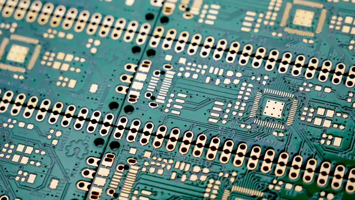
Layers
A printed circuit board can have one layer or many. Each layer does something important. The top and bottom layers hold copper traces and pads. These are for putting on pcb parts. Boards with more than two layers have extra copper inside. These inner layers carry signals, power, or ground.
Single-layer pcbs are easy and cheap. They are good for simple circuits.
Double-layer pcbs give more space and lower noise.
Multilayer pcbs have four or more layers. They use special stack-ups to keep power, ground, and signals apart. This helps signals stay clear and stops problems.
Putting signal layers next to ground layers helps control speed and lowers issues.
Good pcb design uses the right number of layers for the job. More layers make smaller and stronger devices, but cost more.
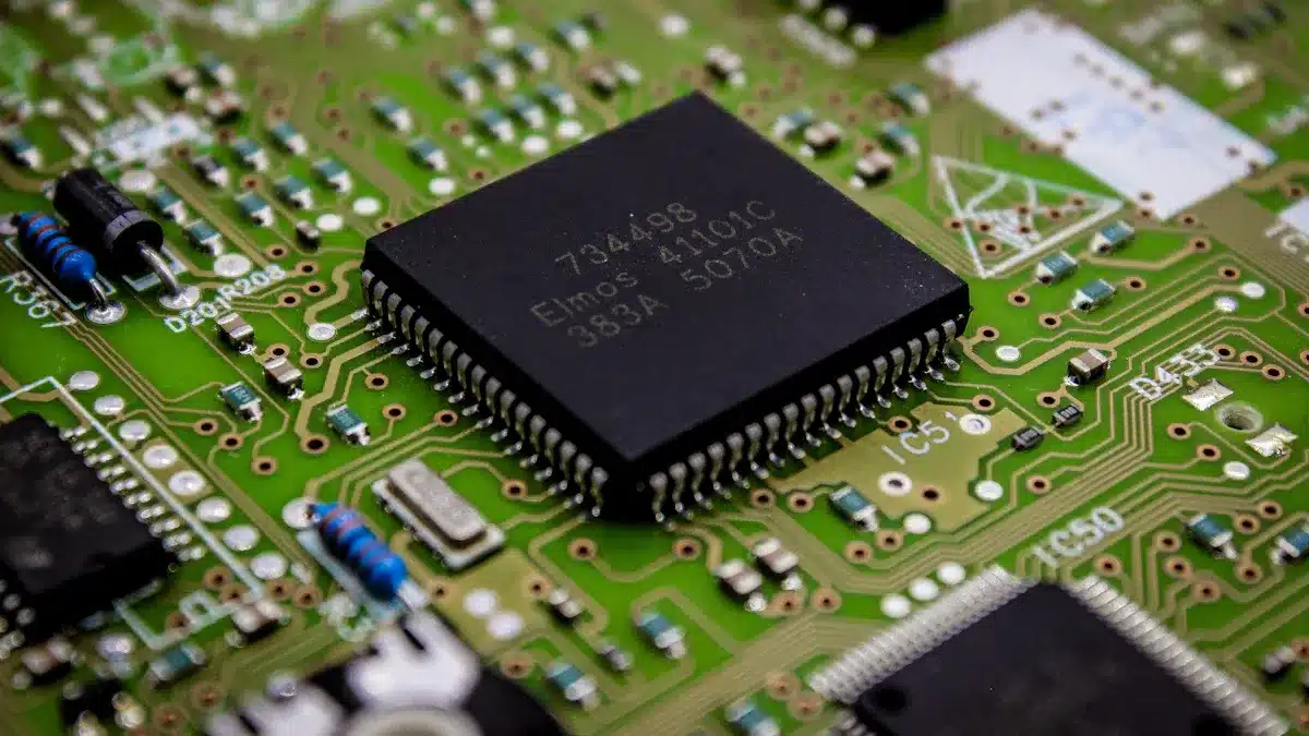
Components
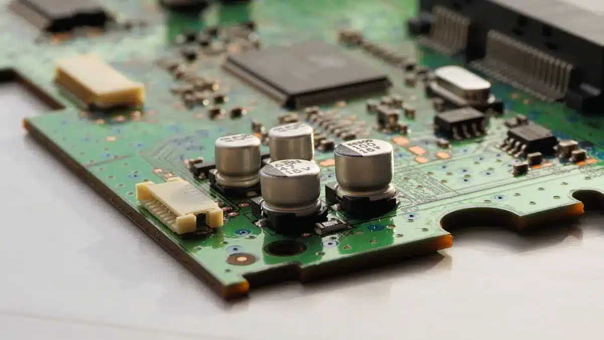
Printed circuit boards hold many electronic parts. Each part has a job in the circuit. Common pcb parts are:
Capacitors: Store and release energy, filter signals, and smooth power.
Inductors: Store energy in a magnetic field, used for filtering.
Diodes: Let current go one way, protect circuits.
Transistors: Work as switches or amplifiers.
Integrated Circuits (ICs): Do hard jobs like processing and memory.
Connectors: Link the board to other things.
Sensors: Notice changes like light or temperature.
Designers put these parts in smart places on the board. This keeps signals clean and stops heat from building up. A good layout helps the pcb work well and last longer.
Tip: Placing pcb parts carefully and picking the right layers makes printed circuit boards work better and last longer in all electronics.
Types of PCBs
Single-Layer
A single-layer pcb has one copper layer. This layer carries electricity. The parts go on the other side of the board. These boards do not use vias or plated-through holes. This makes them easy to make and put together. Single-layer pcbs cost less and last a long time for simple jobs.
Some things that use single-layer pcbs are:
Calculators
Remote controls
Radios
LED lights
Power supplies
Car dashboards
Single-layer pcbs are best for easy circuits. They do not need to be fast or hold many parts.
Double-Layer
Double-layer pcbs have copper on both sides. Vias link the two layers together. This lets people make harder circuits. Double-layer pcbs can hold more parts and send signals better than single-layer boards.
Here is a table that shows how single-layer and double-layer pcbs are different:
Feature | Single-Layer PCB | Double-Layer PCB |
|---|---|---|
Copper Layers | 1 | 2 |
Design Complexity | Simple | More flexible, complex |
Applications | Basic electronics | Industrial, IoT, medical |
Cost | Low | Medium |
Double-layer pcbs are used in factories, phones, cars, and hospitals.
Multi-Layer
Multi-layer pcbs have three or more copper layers. These boards let engineers fit lots of parts in small spaces. Multi-layer pcbs make devices smaller and lighter by putting many boards together.
Some good things about multi-layer pcbs are:
Lighter weight
Cheaper for big orders
Work better for hard circuits
Multi-layer pcbs are found in cell phones, GPS, hospital tools, and planes.
Flexible and Rigid
Flexible pcbs can bend and twist. They fit in things that move or need to save space, like smart watches and bendy phones. Rigid pcbs stay flat and strong. They are good for planes, the army, and cars.
Rigid-flex pcbs mix both types. They are strong and can bend. These boards are used in hospital tools, cameras, and small gadgets.
People pick flexible or rigid pcbs for these reasons:
Fewer connections, so they break less
Fit odd shapes
Resist shaking and tough places
Tip: Picking the right pcb type helps devices work well and last longer.
Importance of PCBs
Reliability
Printed circuit boards help hold and connect electronic parts. They give a strong base for parts and make sure electricity flows well. Engineers plan each pcb to give steady power and stop signal problems. They also protect the board from bending and heat. Good design and tough materials help the board last longer.
The table below shows how different parts of pcb design help make boards reliable:
Aspect | Contribution to Reliability | Key Design Considerations and Effects |
|---|---|---|
Electrical Reliability | Gives steady power and stops signal problems. | Stops crosstalk, uses shields, and keeps return paths close to traces. |
Mechanical Reliability | Keeps solder joints and traces safe from damage. | Uses stiffeners, underfill, and checks for drops. |
Thermal Reliability | Moves heat away from hot parts to stop failures. | Adds thermal pads, spreading planes, and thermal vias; thinks about airflow and dust. |
Thermomechanical Reliability | Handles hot and cold changes to stop cracks and breaks. | Sizes solder lands, controls solder, and follows package rules. |
If a pcb gets damaged, it can cause big problems. Broken boards, bad parts, or cut traces can make devices lose power or stop working. Drops, hits, too much heat, and bad soldering are common causes. Dust, water, and bugs can also hurt the board. When a pcb fails, the device may break or need expensive fixes.
Tip: Clean boards often, store them safely, and test them to keep pcbs working well and help devices last longer.
Miniaturization
Modern electronics are smaller and lighter because of new pcb technology. Engineers use careful methods to put tiny parts close together. Surface Mount Technology and High-Density Interconnect pcbs let more parts fit on one board. Flexible and rigid-flex pcbs can bend, so they work in wearables and folding devices.
Here are some ways pcbs help make things smaller:
SMT lets tiny parts sit right on the board.
Rigid-flex and flexible pcbs mix strong and bendy parts for small designs.
New materials allow thin layers and close parts.
Machines check small boards to make sure they work well.
Phones, smartwatches, earbuds, and medical implants all use small pcbs. These boards help make electronics easy to carry, work better, and do more things.
Note: Small pcbs help signals stay clear and keep heat under control, which is important for small devices to work well.
Applications
PCBs are used in almost every field. They hold and connect parts in medical, travel, home, and factory devices. Each board type fits its job, like flexible pcbs in medical tools or aluminum boards in car lights.
Medical devices: Pacemakers, hearing aids, and fitness trackers use flexible and HDI pcbs for small size and trust.
Consumer electronics: Phones, tablets, cameras, and TVs use small, low-cost pcbs.
Automotive: Cars use pcbs in dashboards, lights, safety, and radar. Flexible boards handle shaking and heat.
Industrial equipment: Power supplies and machines use tough pcbs for hard jobs.
LED lighting: Aluminum pcbs help control heat in lights for homes, cars, and hospitals.
PCBs also let many features work in one device. Engineers make systems with more than one board to do different jobs, making fixing and upgrades easier. This helps complex electronics work better.
Callout: How a pcb is made and its quality decide how safe, reliable, and efficient the product is. Bad design or damage can cause breakdowns, cost more, and make things unsafe.
Printed circuit boards help electronic devices work and look better. They link parts like resistors and microchips. They act like the nervous system for technology. New designs, such as multilayer and flexible boards, make electronics smaller. These boards also make devices faster and more reliable.
People use printed circuit boards in phones, cars, and medical tools. Learning how these boards work helps people see why devices last longer. It also shows why things cost less and have more features.
Key points about printed circuit boards:
They let complex circuits fit in small spaces.
They help many industries, like consumer electronics and aerospace.
They make products flexible, strong, and better for the environment.
FAQ
What is the difference between printed circuit boards and printed wiring boards?
Printed circuit boards and printed wiring boards are the same thing. Both names mean boards that link electronic parts with copper lines. Printed wiring boards is an older name. Most people now say printed circuit boards.
How do printed circuit assemblies work in electronics?
Printed circuit assemblies keep electronic parts in place on a board. They let electricity move between the parts. These assemblies help things like phones and cars work by giving power and signals to each part.
What steps are involved in pcb manufacturing?
Pcb manufacturing begins with making a design for the board. Makers print copper lines, add layers, and put on parts. They test the board to find any problems. This makes strong boards for many devices.
Where are circuit card assemblies used?
Circuit card assemblies are found in many places. People use them in medical tools, cars, computers, and home electronics. These assemblies help devices work well and last a long time.
See Also
Understanding PCBA And Its Function In Electronics
The Importance Of PCBA In Modern Electronic Systems
Defining PCBA And Its Purpose Within Electronic Devices