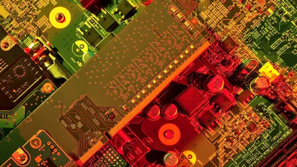

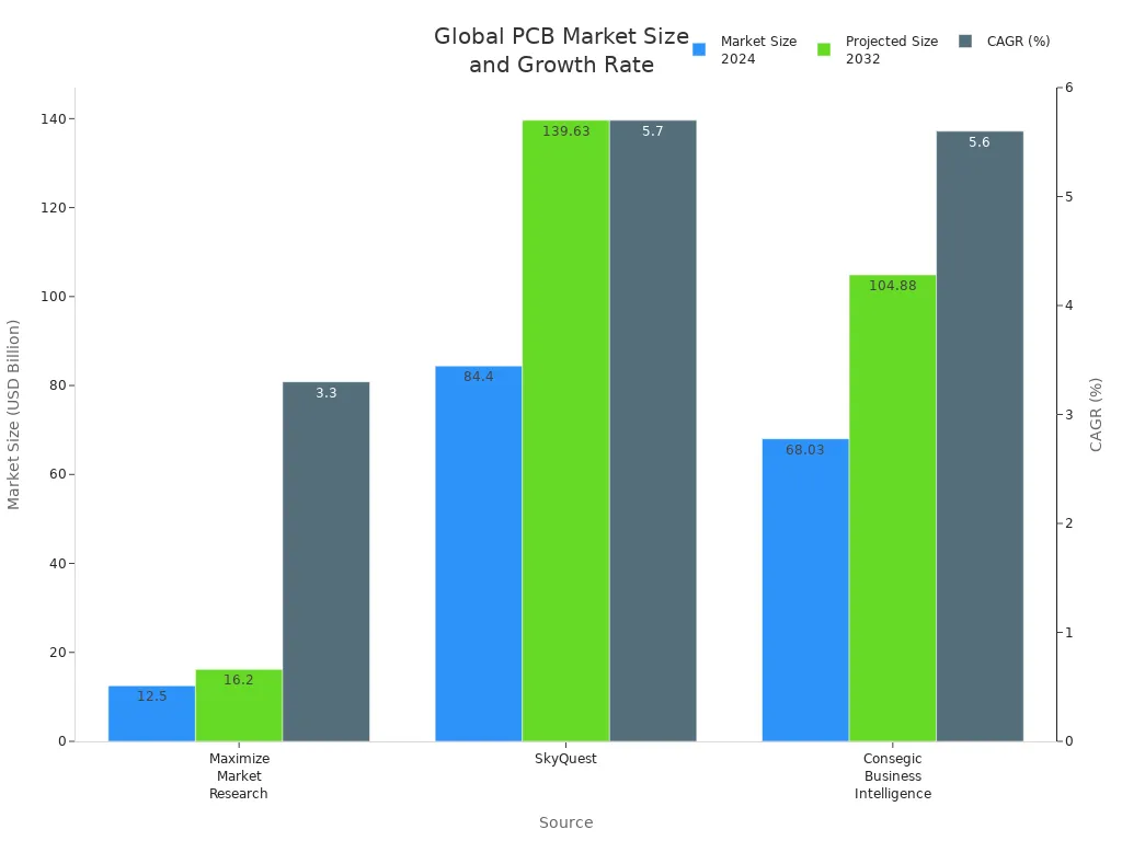
In today’s world, you see PCB circuit boards in almost every electronic device. These boards are very important. They connect and power different parts. The global market for PCB circuit boards is growing fast. It is expected to reach USD 84.4 billion by 2032. This shows a growth rate of 5.7% each year.
PCBs are important in many devices, like:
Computers
TVs
Radios
Cell phones
Digital cameras
Automotive applications
Telecommunication devices
Healthcare equipment
Energy and power systems
Military and utility devices
Knowing about these circuit boards and their parts is key to understanding modern electronics.
Key Takeaways
PCBs are very important for connecting and powering electronic devices. They are the main part of modern technology.
Knowing the different types of PCBs—single-sided, double-sided, and multi-layer—helps you pick the right one for your project.
Important parts like resistors, capacitors, and diodes are key to how PCBs work. They help devices run smoothly.
The PCB market is growing fast. This is because of new technology and the need for smaller, better devices.
Learning about how PCBs are made can help you design and create your own circuit boards well.
What is a PCB Circuit Board?
Definition and Purpose
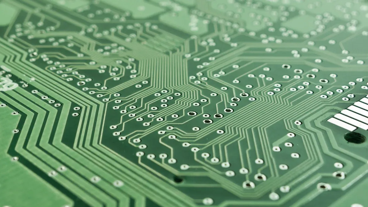
A PCB circuit board, also called a printed circuit board, is very important in today’s electronics. It has layers that are both conductive and insulating. This design helps the PCB connect different electrical parts well. The board has traces that work like wires. They help make electrical connections and hold components in place.
PCBs have several key jobs in electronic devices:
They connect parts in electronic devices.
They help parts communicate with each other.
They allow different electronic devices to work.
You can think of a PCB as the backbone of your gadgets. It sends electrical signals between parts and carries data and instructions through copper paths. Without PCBs, many devices would not work like they do now.
Importance in Electronics
The role of PCB circuit boards in electronics is very important. They make electronic devices more reliable and ensure careful design of connections. PCBs also hold components securely, which is crucial for how well the device works.
“PCBs are the backbone of electronic devices because they help them operate and function.”
Over time, PCB technology has changed a lot. Miniaturization has improved PCB design and abilities. This change has allowed for devices that once seemed like science fiction. Now, you can enjoy small and powerful gadgets in your daily life.
PCB Components
Knowing the parts of a PCB circuit board is important. Each part has a special job to help the board work well.
Conductors
Conductors are materials that let electricity flow easily. Copper is the most common conductor in PCB circuit boards. It makes the traces that connect different parts. The type of conductor affects how well the PCB works. For example, the substrate gives support and keeps electricity from leaking between layers.
Here are some key properties of common conductor materials:
Property | Value Range |
|---|---|
Dielectric Constant (Dk) | 3.5 to 5.5 |
Dielectric Loss Tangent (Tan δ) | 0.02 to 0.001 |
Volume Resistivity (ρ) | 10^3 to 10^10 Megaohm-centimeters |
Electrical Strength | 800 to 1500 V/mil |
The most used PCB material is FR-4. This is a mix of woven fiberglass and epoxy resin. It provides insulation between copper layers while also conducting electricity. Its dielectric constant is about 4.0, making it good for many uses.
Insulators
Insulators are materials that stop electricity from flowing. They are very important for keeping PCB circuit boards safe and strong. Insulating materials help control heat, protecting sensitive parts from getting too hot. They also give support, making sure the board stays whole during making and use.
Here are some common types of insulators used in PCBs:
Thermal Characteristics | Electrical Characteristics | |
|---|---|---|
FR-4 | Tg of 130°C to 140°C, good thermal stability | Dielectric constant (Dk) ranges from 4.0 to 4.8, good electrical insulation |
Polyimide | Tg above 200°C, excellent thermal stability | Flexible, good chemical resistance, low outgassing |
Rogers Laminates | Low dielectric constant (2.2 to 3.0), good thermal conductivity | Low dissipation factor, superior signal quality for RF applications |
These insulating materials stop unwanted electrical problems and shorts, keeping electrical signals clear.
Common Components
Many common electronic parts are found on PCB circuit boards. Knowing what they do helps you see how everything works together. Here are some of the most common parts:
Resistors: Control electric current by turning electrical energy into heat. They limit current and divide voltage.
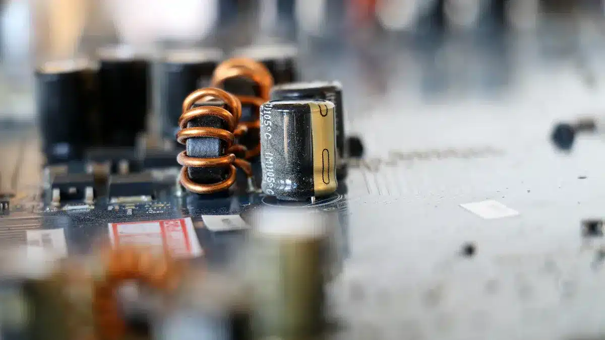
Capacitors: Temporarily store electric charge and filter energy. They are used for coupling, filtering, tuning, and energy storage.
Diodes: Control and change energy flow, letting current go in one direction only. They are important for rectification, detection, voltage regulation, and switching.
Each of these parts is important for how the PCB circuit board works. Together, they make sure your electronic devices run smoothly and efficiently.
Types of PCBs
There are different types of PCB circuit boards. Each type has special features and uses. Knowing these types helps you pick the right one for your project.
Single-Sided
Single-sided PCBs have all their wires on one side. This makes them easier to design and cheaper to make. Here are some important points:
Characteristic | Description |
|---|---|
Single Conductive Layer | All wires are on one side, making the layout simple. |
Double-Sided Component Placement | Parts can be placed on both sides, using space better. |
Plated Through Hole (PTH) Interconnects | Connections between the top and bottom are made with plated holes. |
Limited Interconnect Density | It’s harder to connect many parts because there is only one layer. |
Lower Performance Thresholds | They perform worse than multilayer boards, affecting speed and power use. |
You often see single-sided PCBs in simple devices. They are used in:
Consumer Electronics: Simple items like calculators, remotes, and radios.
Power Supplies: Used in basic circuits for battery chargers.
LED Lighting Systems: Great for simple connections in LED lights.
Automotive Applications: Found in easy systems like dashboard lights.
Double-Sided
Double-sided PCBs have wires on both sides. This design allows for more complicated uses. Here’s how they differ from single-sided boards:
Feature | Single-Sided PCB | Double-Sided PCB |
|---|---|---|
Structure | Parts and wires on one side only | Parts and wires on both sides |
Complexity | Good for simple uses | Good for complex uses |
Component Density | Fewer parts can fit | More parts can fit because of both sides |
Circuit Design | Simpler designs | More complex designs possible |
Application Scenarios | Basic electronic devices | Advanced devices needing more parts |
Double-sided PCBs allow for better connections and can hold more parts. They are cheaper and easier to make than multilayer boards. This makes them a popular choice for many gadgets.
Multi-Layer
Multi-layer PCBs have three or more layers of wires separated by insulating layers. They are important for modern electronics because they can handle complex designs. Here’s what you should know:
Construction Details | Typical Layer Count |
|---|---|
Multi-layer PCBs have three or more wire layers separated by insulation. | Common types include 4-layer, 6-layer, 8-layer, and even more for very dense designs. |
These boards help reduce problems like stray signals and interference. They are great for high-performance uses, being small and providing strong signals. However, they can be hard to make and cost more to design.
PCB Manufacturing Process
The PCB manufacturing process has several important steps. Each step is necessary to make a working circuit board. Here’s a simple look at the main phases:
Design and Layout
In the design and layout phase, you decide what the PCB will do. Follow these steps to make a good design:
Goal Definition and Conceptualization: Figure out what the PCB should achieve.
Schematic Creation: Make a detailed circuit diagram and list of parts (BOM).
Component Selection and Placement: Pick parts and place them carefully based on different factors.
PCB Routing and Draft Schematic Finalization: Connect the electrical paths and finish the diagram.
Testing and Validation: Check to make sure the layout meets all needs.
You can use different software tools for this phase, like:
Altium Designer: Known for its great features and easy use.
Autodesk EAGLE: Has a simple interface for design tasks.
Etching and Printing
After finishing the design, you go to the etching and printing phase. This step makes the actual copper paths on the PCB. Here are the main processes:
Design Transfer: Move the layout using design software.
Photoresist Application: Put a light-sensitive layer on the copper surface.
Exposure and Development: Shine UV light on the board to harden the photoresist in certain areas.
Etching: Soak the board in a solution to remove unprotected copper.
Photoresist Removal: Take off the leftover photoresist to show the copper paths.
You can pick different etching methods, like wet etching with ferric chloride or dry etching with plasma. The materials used, like copper-clad laminate and photoresist, are important for getting accurate results.
Assembly and Testing
The last phase is putting together the parts and testing the PCB. Follow these steps to make sure it’s good quality:
DFA: Verifies Gerber/ODB++ and BOM: Check the design for assembly.
SMT Assembly Process: Use a machine to place components.
Through-Hole Assembly: Put through-hole parts in by hand or with machines.
Cleaning of Assembled Boards: Get rid of flux and dirt.
Final Inspection and Testing: Do quality checks for any physical or electrical problems.
During testing, you might find common issues like solder bridges or not enough solder. Fix these problems with visual checks and automated tests. By following these steps, you make sure your PCB works well and meets industry standards.
In conclusion, PCB circuit boards are very important in today’s electronics. They help make devices smaller, improve performance, and ensure they work well. Here are some main points:
The PCB market is expected to grow a lot due to new technology.
Trends in sustainability are changing how PCBs are designed and made.
As technology changes, PCBs will be even more important in your daily devices. Knowing about their parts and types will help you make smart choices in your electronic projects. 🌟
FAQ
What materials are PCBs made from?
PCBs are usually made from materials like FR-4. This is a mix of woven fiberglass and epoxy resin. Other materials include polyimide for flexible designs and Rogers laminates for high-frequency uses.
How do I choose the right PCB type?
Pick a PCB type based on what your project needs. For simple designs, use single-sided boards. For more complex circuits, think about double-sided or multi-layer boards. They offer better performance and can hold more parts.
Can I design my own PCB?
Yes, you can design your own PCB. Use software like Altium Designer or Autodesk EAGLE. These tools help you make schematics, layout designs, and prepare files for making the board.
What is the role of solder in PCBs?
Solder connects electronic parts to the PCB. It makes a strong electrical and mechanical bond. This ensures reliable connections. Good soldering techniques are very important for how well the device works.
How can I troubleshoot a faulty PCB?
To troubleshoot a faulty PCB, first check for damaged parts or solder bridges. Use a multimeter to test connections and voltages. Testing each part can help find the problem.
See Also
Essential PCBA Components And Their Important Roles
The Functionality Of PCBA Motherboards And Its Significance
An Overview Of PCBA Coating Types And Fundamentals