A circuit card assembly, or CCA, is a board. It holds and connects electronic parts. This helps devices work the right way. Circuit card assemblies are the main part of most gadgets. They are in things like phones and medical tools. People who work with electronics see more need for circuit card assemblies. This is true in places like aerospace and medical devices. The job of a CCA changes how well a device works. Knowing how a circuit card works helps many people. It helps users, engineers, and buyers understand electronics. Every circuit card changes how a device works.
Key Takeaways
Circuit card assemblies keep electronic parts in place and connect them. They help devices like phones and medical tools work right. They let devices be smaller, lighter, and stronger by putting many parts close together. The making process has careful steps like soldering and testing. This makes sure the quality is high and the parts work well. Good circuit card assembly helps devices work better and last longer. New technology in circuit card assembly lets us have cool things like bendy electronics and faster devices for talking.
What Is Circuit Card Assembly
CCA Definition
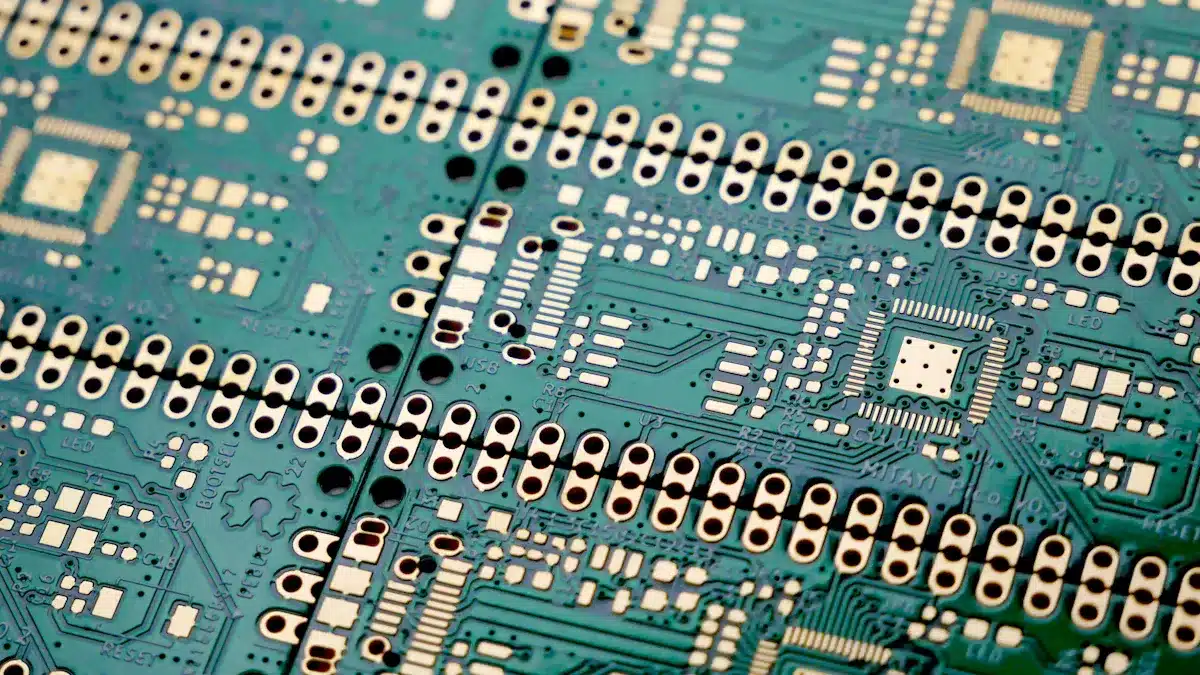
A circuit card assembly is a board that holds electronic parts. It connects these parts so a device can work. People also call it a circuit card or CCA. The circuit card is flat and made from fiberglass. Thin lines called traces link the parts together. These parts can be chips, resistors, or capacitors. The circuit card assembly puts all these parts in one place.
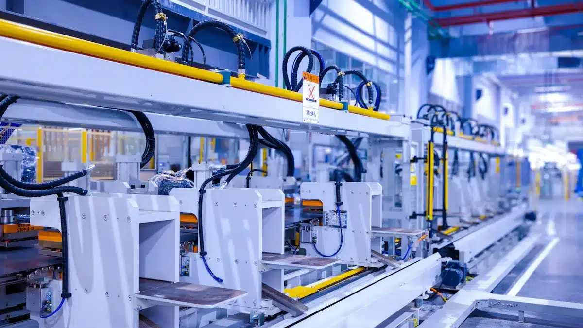
Making a circuit card assembly takes many steps. Each step helps the circuit card work well and last longer.
1. Solder paste printing on circuit cards: Workers put solder paste on the pads using a stencil. 2. Solder paste inspection: Machines check the solder paste for the right shape and amount. 3. Placing SMDs on circuit boards: Machines place small parts onto the circuit card. 4. Reflow soldering: The circuit card goes through heat to melt the solder paste and attach parts. 5. Automatic optical inspection: Machines look for mistakes or missing parts on the circuit card. 6. Inserting pins of through-hole components: Workers or machines put parts with pins through holes in the card. 7. Preheating and wave soldering: The card moves over liquid tin to solder the pins. 8. Trimming and final visual inspection: Workers cut extra pins and check the card for problems. 9. Final electrical testing: Testers use tools to make sure the circuit card assembly works right.
This careful process helps each circuit card assembly meet high standards for safety and quality.
Backbone of Electronics
Circuit card assemblies are very important in most modern devices. They connect and power all the electronic parts. Without a circuit card, things like phones and computers would not work.
Note: Circuit card assemblies are used in many places. They help devices in homes, factories, hospitals, and airplanes.
Application Area | Examples / Description |
|---|---|
Smartphones, laptops, televisions, gaming consoles, home appliances | |
Industrial Electronics | Automation and control systems, power distribution equipment, industrial machinery, measurement and testing equipment |
Automotive Industry | Engine control, infotainment, navigation, safety systems |
Aerospace and Defense | Communication systems, radar, sonar, flight control, weapon control systems |
Medical Devices | Blood glucose monitors, MRI machines, pacemakers, robotic surgical systems |
Telecommunications | Routers, switches, modems, communication satellites |
Energy Systems | Power generation equipment, solar inverters, wind turbines, electric vehicle charging stations |
Circuit card assemblies help make devices smaller and lighter. They let engineers fit more parts into a small space. This makes thin phones, tiny medical devices, and strong computers possible.
Circuit card assemblies help make neat layouts that fit more parts and make devices smaller.
Surface mount technology and small parts help shrink devices but keep them powerful.
Good assembly methods keep connections strong, even in small devices.
Special designs and tools help place small parts, manage heat, and connect tricky circuits.
Small connectors and low-profile parts make devices even smaller, especially in wireless and smart devices.
Circuit card assemblies give engineers what they need to build new products. They help make electronics smaller, faster, and more reliable. Every circuit card helps shape the future of technology.
Circuit Card Assembly vs PCB vs PCBA
PCB Overview
A printed circuit board forms the base for most electronic devices. This board uses layers of materials like FR-4, polyimide, or PTFE. These materials give the board strength, help manage heat, and keep signals clear. The printed circuit board has copper traces that connect different points. It does not have any electronic parts attached. People use printed circuit boards to support and connect circuits. The board stays flat and strong, even when devices get hot or move around.
Tip: The choice of material in a printed circuit board affects how well it works in different environments.
PCBA Overview
A printed circuit board assembly, or PCBA, is a printed circuit board with all its parts attached. Workers or machines place chips, resistors, and other parts on the board. They use methods like surface mount technology or through-hole technology. Soldering holds each part in place. After assembly, the board can do its job in a device. Many people also call this a circuit card assembly. The circuit card now has all the parts it needs to work. This step turns a simple board into a working circuit card.
Key Differences
The main difference between a printed circuit board and a circuit card assembly is the parts. A printed circuit board is just the board with copper traces. A circuit card assembly has all the parts mounted and ready to use. People often use the terms PCBA and circuit card assembly for the same thing. Both mean a board with parts attached. Sometimes, a circuit card can be part of a bigger system called a Box Build. This system includes the circuit card, wires, and even the case.
Aspect | Printed Circuit Board (PCB) | Circuit Card Assembly (CCA) / PCBA |
|---|---|---|
Structure | Bare board, no parts | Board with all parts attached |
Function | Supports circuits | Performs electronic tasks |
Appearance | Flat, with copper lines | Has chips, resistors, connectors |
Use | Base for assembly | Ready for use in devices |
There are many types of circuit card assembly. Some use only surface mount parts. Others use both surface mount and through-hole parts. Each type of circuit card fits a different device or job. The right type of circuit card assembly helps devices work better and last longer.
Circuit Card Assembly Components
A circuit card assembly needs many important parts to work. Each part helps the circuit card do its job.
Substrate & Traces
The substrate is the base of the circuit card. It holds all the parts in place and makes the board strong. Different materials are used for different jobs:
FR4 is the most common substrate. It is a strong glass material that does not burn easily.
CEM materials, like CEM-1 to CEM-5, are good for electricity and strength.
Teflon (PTFE) is used when the circuit card gets hot or needs to handle fast signals.
Polyimide is used for flexible circuit cards. It lets the board bend without breaking.
Rogers materials are used for fast and high-frequency circuits.
Traces are thin copper lines on the substrate. They connect the electronic parts and let signals move around. The type of substrate and how the traces are placed change how well the circuit card works.
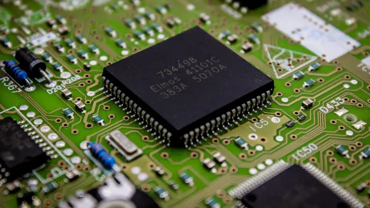
Electronic Parts
Electronic parts are very important for the circuit card. These parts help control, store, and move signals. Some common parts are:
Capacitors
Inductors
Diodes
LEDs
Transistors
Crystals and oscillators
Relays and switches
Integrated Circuits (ICs)
Engineers use surface mount and through-hole ways to put these parts on the board. The right mix of parts helps the circuit card assembly do many things, from simple to hard tasks.
Note: Circuit card assemblies have both passive and active devices. Each kind of part does something special for the circuit card.
Connectors
Connectors join the circuit card to other boards or devices. They move power, data, and signals in and out. There are different kinds of connectors:
Board-to-board connectors link more than one circuit card together.
I/O connectors, like USB, HDMI, and Ethernet, help send data and power to other devices.
Wire-to-board connectors connect things like sensors or motors to the board.
High-frequency connectors keep signals strong for radio or microwave circuits.
FPC/FFC connectors work with flat cables in thin devices.
Choosing the right connector helps the circuit card assembly fit and work well. Through-hole connectors are strong and hold tight. Surface mount connectors save space on the board. The best connector makes sure the circuit card assembly works right in its device.
Circuit Card Assembly Manufacturing Process
Design & Layout
The process starts with careful planning and design. Engineers use special computer programs to plan the circuit card assembly. Some popular tools are:
Altium Designer helps with hard designs and drawing circuits.
Eagle is easy to use and has many good features.
KiCad is free and works for both new and skilled users.
These programs help engineers make a design that is simple to build and works well. Good planning makes the next steps easier.
Component Mounting
After planning, workers or machines put parts on the board. Surface-mount technology puts small parts right on top of the board. Through-hole technology puts parts with pins into holes. The best way depends on the type of circuit card assembly and what the device needs.
Soldering Methods
Soldering sticks the parts to the board. There are two main ways to solder. The table below shows how they are different:
Aspect | Wave Soldering | Reflow Soldering |
|---|---|---|
Soldering Process | Uses a wave of melted solder to join parts. | Uses solder paste and heat to stick parts. |
Component Suitability | Best for through-hole parts. | Best for surface-mount technology (SMT) parts. |
Temperature Range | 250°C – 270°C | 235°C – 250°C |
Production Efficiency | Sells many boards at once. | Sells one board at a time. |
Equipment Cost | $50,000 – $300,000 | |
Quality and Reliability | Makes strong joints but can have problems. | Has good control and fewer mistakes. |
Advantages | Fast for making lots of boards. | Good for small and tricky boards. |
Disadvantages | Not for crowded boards; can have mistakes. | Costs more; needs careful design. |
Common Defects | Solder can bridge or make cold joints. | Can cause tombstoning or empty spots. |
Picking the right soldering way helps make strong and safe circuit card assemblies.
Quality Control
Quality control is very important in making circuit card assemblies. Companies use rules like ISO 9001 for quality and UL 796 for safety. They also follow RoHS and REACH to keep out bad chemicals. Quality checks have many steps:
Design for Manufacturability checks if the design is easy to build.
Automated Optical Inspection finds problems in solder and parts.
Time Domain Reflectometer Testing checks signal paths.
Flying Probe Test uses moving probes to test the board.
First Article Inspection checks the first boards made.
Visual and microscope checks look for small problems.
In-circuit tests check connections.
X-ray checks look inside the board.
Saw checks cut boards to see inside.
Functional testing makes sure the board works.
Camera checks give clear pictures.
Manufacturers count problems using Defects Per Unit and Defects Per Million Opportunities. These numbers help make the process better and make sure each circuit card assembly is high quality.
Tip: Skilled workers and strong quality checks keep the process safe and reliable. This makes sure every circuit card assembly works the right way.
Role of CCA and Significance in Modern Electronics
Device Performance
The role of cca affects how well devices work. Engineers use circuit card assembly to fit more parts in less space. This makes devices lighter and smaller. Advanced PCB layering helps build complex circuits. It also lets engineers add more parts to one board. Devices like smartphones need these features to stay small and strong. Multilayer boards help signals stay clear and reduce noise. Careful design keeps signals working right, even in hard systems. New materials and machines help fix heat and connection problems. The number of layers depends on what the device needs.
Testing is important for device performance. Automated Optical Inspection finds problems early. In-Circuit Testing checks if parts work right. Functional testing makes sure the board does its job. These tests help only good boards reach customers. High first pass yield means most boards pass the first time. Low defect rates show the assembly is good. Devices with strong circuit card assembly last longer and work better.
Performance Metric | Description |
|---|---|
First Pass Yield (FPY) | Percentage of assemblies passing quality checks on the first attempt; higher FPY means fewer reworks and better quality. |
Defect Rates | Frequency of defects detected during testing; lower defect rates indicate higher assembly quality. |
Functional Test Pass Rate | Percentage of assemblies passing functional testing, ensuring electrical functionality and reliability. |
Overall Reliability | Long-term performance and durability of the device, directly influenced by assembly quality. |
Reliability
The role of cca also helps devices stay reliable for a long time. Many things can make a circuit card assembly fail. Soldering problems, mistakes, and old parts all matter. Soldering defects like cold joints or bridges can stop a device. Human errors, like using the wrong part, can cause failures too. Over time, materials can break down and parts can stop working.
Soldering problems include open spots, too much solder, and parts moving.
Human mistakes happen when workers read directions wrong or skip steps.
Aging makes materials weak and parts stop working.
Manufacturers try to stop these problems. They train workers and check quality often. They follow industry rules to lower failures. Automated checks and reviews catch mistakes early. Ongoing tests and skilled workers keep devices running longer. Picking good materials and balanced designs helps stop warping and cracks.
Failure Mode | Description / Examples | Mitigation Strategies |
|---|---|---|
Soldering Defects | Cold joints, solder bridging, tombstoning, solder balling, lifted pads, webbing, etc. | Design review before assembly, proactive design approach, rigorous testing, and quality control (AOI) |
Improper Component Placement | Components too close, wrong orientation or location | Design for Manufacturing (DFM) analysis to optimize placement and component selection |
Board Warping | PCB shape alteration causing assembly issues | Balanced board design, careful heat/force application during assembly, experienced manufacturing team |
Electrical Noise | Noise from spikes, poor grounding, high-frequency interference | Proper PCB layout, inclusion of ground planes, strong design team involvement |
Elastic/plastic deformation, brittle fracture, fatigue, warpage | Use of appropriate materials, controlled manufacturing processes, embedded passives to avoid solder failures | |
Human Errors | Misreading polarity, incorrect part loading, incomplete testing | Process discipline, adherence to IPC standards, well-trained assemblers |
Aging | Material degradation, component failure over time | Ongoing reliability testing, root cause failure analysis, aftermarket repair and rework |
The role of cca in reliability means fewer repairs and less downtime. This makes users happier.
Innovation & Trends
The role of cca helps bring new ideas to electronics. High-Density Interconnect technology lets engineers add more features to small devices. Flexible and stretchable boards let electronics bend and fit new shapes. These advances help make wearables, medical sensors, and curved screens.
HDI technology helps make tiny, powerful devices like smartwatches.
Flexible PCBs let engineers build bendable and wearable electronics.
New materials handle fast signals for 5G and radar.
Embedded parts inside the board save space and boost power.
3D-printed electronics help make new designs quickly.
AI and machine learning help design, find defects, and speed up production.
Knowing about cca helps engineers make better products. They can pick the right materials and plan good layouts. They use the best ways to put boards together. This helps signals stay clear, heat move away, and devices stay strong. Engineers who know about circuit card assembly work better with manufacturers. They can fix problems faster.
Buyers also gain from knowing about cca. They can choose suppliers with good quality checks and support. Buyers look for vendors who test boards, deliver fast, and give clear paperwork. They also check if the supplier can make special boards or custom designs.
Note: Circuit card assembly is important because it helps make smaller, faster, and stronger devices. The role of cca links design, building, and use. This makes it important for everyone in electronics.
A circuit card assembly is like the heart of electronics. It connects and holds all the important parts. Here are some things to remember:
Circuit card assemblies help make small, strong, and fast devices.
They put many parts together so electronics work right.
Knowing about them helps people pick better technology.
If you want to learn more, check out SparkFun tutorials or Versa Electronics articles. These resources can teach you more about how electronics are made and designed.
FAQ
What is the main job of a circuit card assembly?
A circuit card assembly connects and holds electronic parts. It lets electricity flow between parts. This helps the device work as planned.
How does a CCA differ from a PCB?
A PCB is just the board with copper lines. A CCA has the board plus all the electronic parts attached. The CCA can work in a device.
Why do engineers use surface mount technology?
Engineers use surface mount technology to fit more parts on a small board. This method helps make devices smaller and lighter.
Can a CCA be repaired if it stops working?
Yes, skilled workers can often repair a CCA. They find broken parts, replace them, and test the board to make sure it works again.
Where can people find more information about CCAs?
Tip: People can visit electronics websites, read manufacturer guides, or watch online tutorials. These resources help explain how CCAs work and how to use them.
See Also
What PCBA Means And Its Importance In Electronics
Benefits And Issues Of Flex PCBA In Today’s Electronics
Exploring The Meaning And Function Of PCBA In Electronics
A Guide To PCBA Definition And Its Main Uses In Electronics
The Function Of PCBA Motherboards And Their Significance Explained