Building electronic circuits lets you be creative and innovative. As you learn about this field, you will see that the market for electronic circuit design and making is doing well. In 2023, it grew to $12.5 billion. It is expected to grow 6.5% each year. This growth shows that more technology is needed in many areas. Knowing the basics of electronic circuits gives you the skills to help in this exciting industry.
Key Takeaways
Learn the basics of electronic circuits. Key parts include resistors, capacitors, and diodes. Knowing these parts is important for building good circuits.
Master soldering skills to make strong connections. Good soldering helps your projects work better and avoids problems later.
Use breadboards for testing. They let you try out and change your circuit designs easily without making permanent connections.
Get to know Ohm’s Law. This rule helps you figure out voltage, current, and resistance. It makes sure your circuits work safely and well.
Use multimeters for fixing problems. They are important tools for measuring voltage, current, and resistance. They help you find and solve circuit issues.
Basic Concepts
What is an Electronic Circuit?
An electronic circuit is a path for electric current. You can see it as a group of parts that connect and work together. These parts include resistors, capacitors, diodes, and transistors. Each part has a special job in managing electricity flow.
In simple words, an electronic circuit can be analog or digital. Analog circuits deal with continuous signals. Digital circuits work with separate signals. Knowing this difference is important for beginners. Here’s a quick comparison:
Parameter | Analog Circuit | Digital Circuit |
|---|---|---|
Definition | Works only with analog signals. | Works only with digital signals. |
Input signal | Continuous time signal. | Discrete time signals. |
Output signal | Gives analog signals. | Gives digital signals. |
Circuit components | Resistors, inductors, capacitors. | Logic gates. |
Need of converters | No converters needed. | Needs ADC and DAC. |
Susceptibility to noise | More affected by noise. | Not affected by noise. |
Design | Harder to design. | Easier to design with software. |
Flexibility | Less flexible. | More flexible. |
Types | Active and passive circuits. | Only active circuits. |
Processing speed | Slower. | Faster processing speed. |
Power consumption | Uses more power. | Uses less power. |
Accuracy & precision | Less accurate and precise. | More accurate and precise. |
Observational errors | Possible errors. | No observational errors. |
Signal transmission | Sent in wave form. | Sent in digital form. |
Form of information storage | Stored in wave form. | Stored in binary form. |
Logical operations | Not good at logical operations. | Good at logical operations. |
Key Electrical Principles
Knowing key electrical principles is important for anyone who wants to build electronic circuits. One key principle is Ohm’s Law. This law says that the current in a conductor between two points depends on the voltage and resistance. You can write this relationship with the formula:
V = I × R
Where:
V is the voltage (in volts),
I is the current (in amperes),
R is the resistance (in ohms).
Here are some practical uses of Ohm’s Law:
Design with Precision: Accurate voltage, current, and resistance calculations help you choose the right parts and avoid circuit problems.
Troubleshoot Issues: Ohm’s Law helps find circuit issues by showing voltage or current differences.
Ensure Safety: Keeping circuits balanced reduces risks like overheating, making projects safer and more reliable.
By understanding these basic ideas, you build a strong base for your journey into electronics. You will see that knowing how circuits work makes building electronic projects easier and more fun.
Key Components
Understanding Resistors and Diodes
Resistors and diodes are important parts of electronic circuits. They have key jobs in how circuits work.
Resistors limit how much electric current can flow. They protect delicate parts from getting hurt. Here are some main jobs of resistors:
Current Limitation: Resistors control how fast electric current flows. This stops damage to parts.
Voltage Adjustment: They change voltage levels by changing how voltage spreads in the circuit.
Circuit Response Adjustment: Resistors change how frequency and amplitude respond.
Current Distribution: In parallel circuits, they share current to different paths.
Voltage Regulation: Resistors help keep voltage steady in circuits.
Diodes let current flow in only one direction. This is important for keeping circuits safe from reverse voltage. Here are some key roles of diodes:
They stop damage from voltage spikes by blocking current going the wrong way.
Diodes are used in clamping circuits to reduce voltage spikes from inductive loads. This protects sensitive parts.
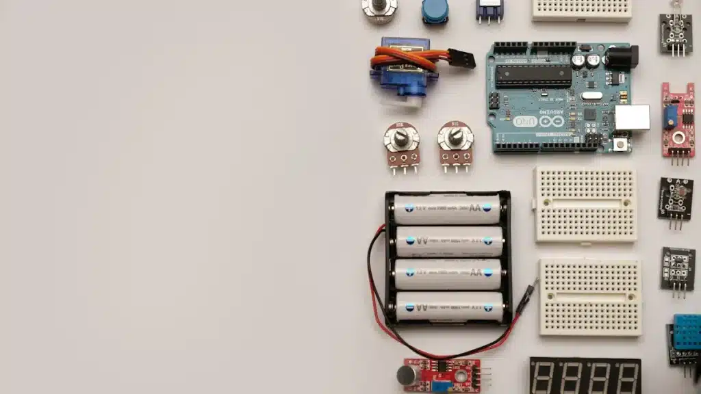
Tools for Circuit Building
To build electronic circuits well, you need the right tools. Here’s a list of must-have tools for your kit:
Multimeter
Soldering Iron and Accessories
Desoldering Tools
Breadboard
Wire Strippers
Helping Hands (Third Hand Tool)
Precision Screwdriver Set
Digital Caliper
Heat Gun
Tweezers
These tools help you check voltage, current, and resistance. A soldering iron puts parts together, while a breadboard makes it easy to test ideas. Wire strippers get wires ready for connections, and helping hands keep parts steady while you work.
By knowing these parts and having the right tools, you can start building electronic circuits with confidence.
How to Build Circuits
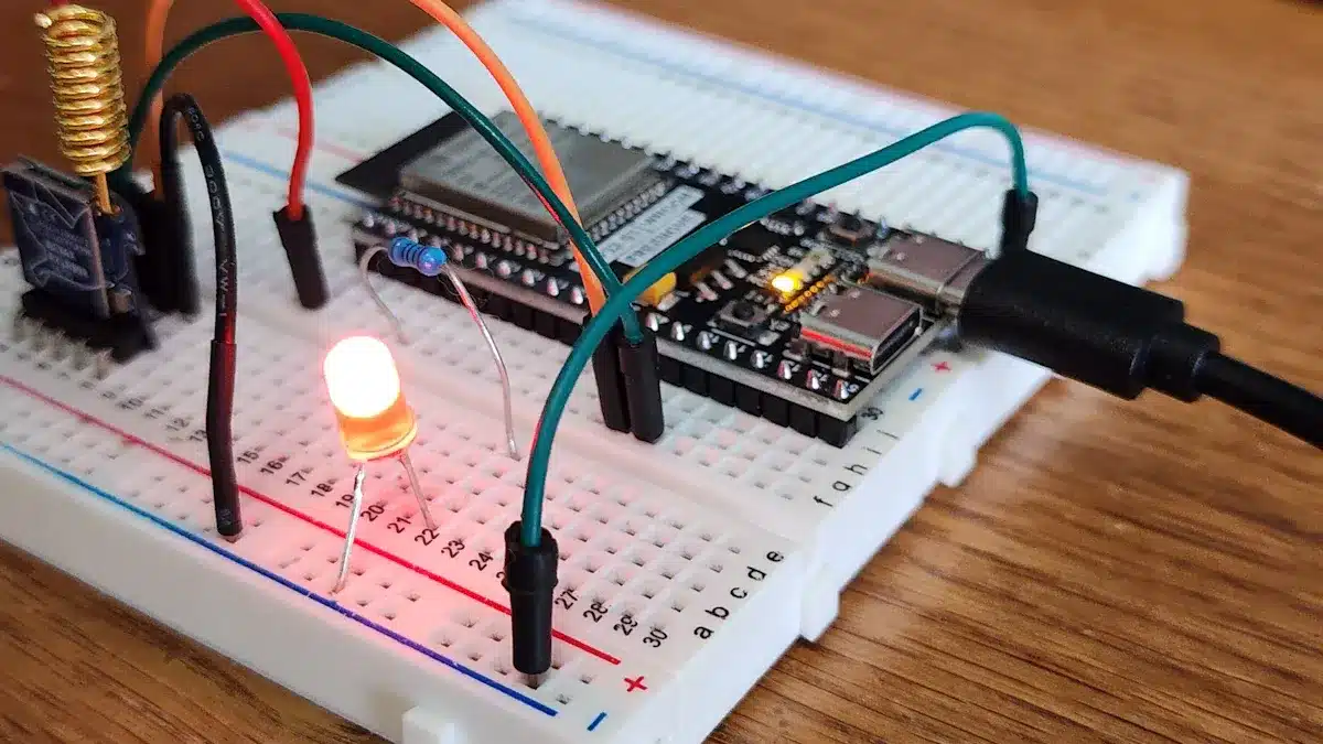
Building electronic circuits can be fun and rewarding. You can start by learning to use a breadboard and practicing soldering. These skills help you make reliable and working circuits.
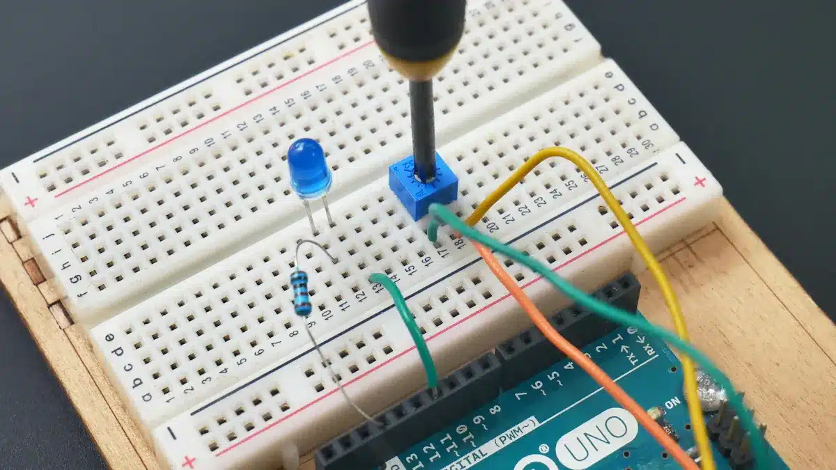
Breadboarding Basics
A breadboard is a tool that lets you build and test circuits without soldering. It makes it easy to try different setups. Here’s a simple guide on how to put together a basic circuit using a breadboard:
Identify the LED: Find the longer leg (anode) and the shorter leg (cathode) of the LED.
Select a Resistor: Pick a 330-ohm resistor for the LED.
Connect the Resistor: Put one leg of the resistor into a breadboard row.
Connect the LED: Attach the LED’s anode to another hole in the same row as the resistor.
Complete the Circuit: Connect the other end of the resistor to a different row and the LED’s cathode to another row.
Power Connections: Connect a wire from the positive power rail to the resistor’s other leg, and another wire from the LED’s cathode to the negative power rail.
Test the Circuit: Turn on the power source and see if the LED lights up.
Tip: Always check the polarity to avoid damaging parts. Use the right wire size for high current projects to stop overheating.
When using breadboards, be careful of common mistakes. Here are some to avoid:
Putting components in the wrong way can cause circuit failure. Make sure each pin is in the right breadboard holes.
Not using current-limiting resistors can harm components. Always add the right resistors, like 1kΩ for BJTs.
Loose connections can lead to problems. Make sure all connections are tight.
Soldering Techniques
Soldering is important for making permanent connections in your circuits. Here are some good practices to follow when soldering parts onto a printed circuit board:
Failure Mode | |
|---|---|
Cold soldering | Design thermal relief or other features to help with soldering. |
Bridging | Check for warpage when choosing large BGA parts for the PCBA. |
Non-wetting | Keep strict quality checks during the raw material process. |
To make strong solder joints, follow these steps:
Use a comfortable soldering iron that is easy to handle.
Make sure the solder is right for PCBs, preferably rosin core solder.
Clean the metal surfaces to remove dirt before soldering.
Melt a little solder on the iron tip to help heat transfer.
Hold the iron against the lead and hole for a few seconds to heat them well.
Feed solder to the heated parts until a good joint forms.
Let the joint cool without putting stress on it.
Note: The quality of your soldering tools affects how strong your solder joints are. Good temperature control and the right solder materials are key for strong connections.
By mastering these techniques, you will improve your ability to build circuits well. With practice, you will feel more confident in your skills and be ready for more complex projects.
Electronic Circuit Design
Designing electronic circuits has some important steps. First, you make circuit diagrams. These diagrams act like blueprints for your projects. They help you see how different parts connect and work together.
Creating Circuit Diagrams
To make good circuit diagrams, follow these steps:
Go to My Documents and start a new document.
Decide what your circuit diagram will do.
Draw the circuit diagram, starting with basic connections.
Add parts and make sure all connections are shown.
Check the diagram for clarity and correctness before using it.
Using software tools makes designing circuits easier. These tools help you create neat diagrams with lots of symbols. Start with simple circuits and then move on to more complex ones. Always double-check your work to make sure connections and parts are correct.
Functionality | Description |
|---|---|
Lets users create diagrams showing circuit parts and how they connect. | |
Circuit Simulation | Helps check circuit designs to find and fix problems before building them. |
PCB Layout | Aids in designing printed circuit boards, deciding where parts go and how they connect. |
Collaboration | Allows teamwork using cloud tools for version control and multiple users. |
Identifying Functional Blocks
Knowing about functional blocks is key in circuit design. Each block has a special job that helps the circuit work. Common functional blocks include:
Description | |
|---|---|
Microphone | Changes sound signals into electrical signals (voltage) |
Pre-Amplifier | Boosts the low-level signal from the microphone to a higher level |
Tone and Volume Controls | Changes high frequency (Treble) and low frequency (Bass) |
Power Amplifier | Increases the power of the audio signal |
Loudspeaker | Turns electrical signals into sound |
Using many functional blocks can make circuits work better. For example, an optical receiver can make the circuit more sensitive. A coherent laser-forwarded BPSK link can send data quickly. By knowing how these blocks work together, you can design better and more effective circuits.
Troubleshooting Circuits
Fixing problems in circuits can be tough. But if you know common issues and how to fix them, it gets easier. You will see different problems when working with electronic circuits. Here are some common issues you might find:
Test Probe Issues: Bad contact or wear can give wrong results. Dirt on probes can also change readings.
Fixture Problems: If probes are not lined up right, they can miss targets. This can cause open circuit errors.
In-Circuit Testing Errors: Wrong test settings or outside factors can cause false results.
Component Accessibility Limitations: Some parts may be hard to test, leading to missing checks.
Software and Calibration Issues: Old software or no calibration can mess up measurements.
To fix circuit problems well, follow these steps:
Check documents and history before starting.
Find out what type of electrical fault it is.
Use the right tools for diagnosis.
Look closely at key connections and parts.
Find the problem and make necessary repairs.
Safely turn the power back on after finishing.
When checking your circuit, look for:
Terminals that are loose or rusty.
Wires that have cracks or signs of stress.
Parts that show physical damage.
In-circuit testing lets you check parts while they stay in the circuit. This method helps find shorts and other problems, but readings might be different from those taken out of the circuit.
Using Multimeters
Multimeters are important tools for finding faults in electronic circuits. They measure voltage, current, resistance, and continuity, which are key for troubleshooting. Here’s how to use a multimeter well:
Set the multimeter dial to the right measurement type: voltage (V), current (A), or resistance (Ω).
For voltage, put the black probe on the negative terminal and the red probe on the positive terminal.
For resistance, make sure the circuit is off and touch the probes to both sides of the resistor.
For current, break the circuit and connect the multimeter in series, using the right port for the current type.
When measuring voltage across parts, you can check if they work correctly. You can also do nodal analysis by measuring voltage drops across parts to ensure they get the right voltage.
A continuity test checks if two points in a circuit are connected. If there is no continuity, it shows a break in the circuit, which is important for troubleshooting. This can help find issues like bad solder joints or wrong wiring.
Tip: Always plug the black probe into the COM port. Use the ‘V ohm’ port for measuring voltage and resistance, and the ‘A’ or ‘mA’ port for measuring current. Be careful when measuring current to avoid blowing a fuse.
By learning these troubleshooting methods and using a multimeter well, you can fix problems in your electronic circuits with confidence.
Building electronic circuits gives you many chances to explore. Here are some important points to remember:
Understand Basic Components: Learn about key parts like resistors, capacitors, and diodes.
Soldering Skills: Get good at soldering to make strong and nice-looking circuits.
Transistor Applications: Use transistors as switches to control things like motors and lights.
Integrated Circuits: Learn how to use integrated circuits to make your projects better.
Design PCB: Learn to design printed circuit boards for more advanced circuits.
Getting these skills can really improve your job chances in engineering and technology. For more learning, check out resources like Electronics Explained The Easy Way and How to Build Circuits. Enjoy the journey of building circuits, and let your creativity shine! 🌟
FAQ
What is the best way to start designing an electronic circuit?
Start by learning about the parts you need. Use a breadboard to test your ideas. Draw a simple circuit diagram to see your design before you build it.
How do I choose the right microcontroller for my project?
Pick a microcontroller that fits your project needs. Think about things like speed, memory, and how many input/output pins you need. Look up different models to find the best one.
Can I use a breadboard for all types of circuits?
You can use a breadboard for most simple circuits. But for more complicated designs, you might need to solder parts onto a printed circuit board. This makes them more stable and reliable.
What tools do I need for circuit design?
You will need some important tools like a multimeter, soldering iron, breadboard, and wire strippers. These tools help you build, test, and fix your circuits well.
How can I troubleshoot my circuit if it doesn’t work?
First, check all the connections and parts. Use a multimeter to check voltage and if the circuit is connected. Find any broken parts and replace them if needed.
See Also
Streamlined PCBA Solutions for Your Electronics Projects
Comprehensive Guide to Manufacturing PCBA Effectively
Innovative Testing Methods for PCBA in Electronics Production
Effective Strategies to Improve Your PCBA Engineering Skills