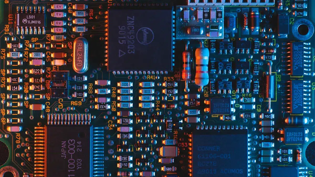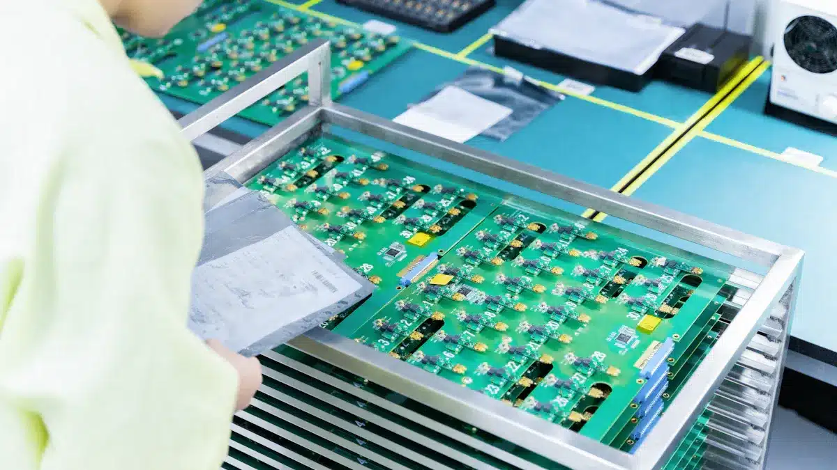
In printed circuit board manufacturing, choosing materials is very important. The materials you pick affect how well the board works and how reliable it is. You need to think about different types of PCB materials. Each type changes how the final product works. For example, substrates like FR-4 provide electrical insulation and strength. Advanced materials like ceramic help with heat management. Knowing these properties helps you choose the right materials. This leads to better results in your electronic devices.
Key Takeaways
Picking the right PCB materials is important. It affects how well the board works and how long it lasts.
FR-4 is the most common material. It is strong, resists moisture, and is cheap.
Flexible materials like polyimide let PCBs bend. This makes them great for small, light devices.
Copper is the main material for conducting electricity. It works well for both electricity and heat at a low cost.
Better materials like metal cores and ceramics help manage heat and improve signal quality. They are good for high-power and high-frequency uses.
PCB Substrates

In printed circuit board manufacturing, picking the right substrate materials is very important. Substrates are the base for the whole PCB. They affect how well it works, how strong it is, and how it handles heat. Knowing about different types of substrates helps you choose the best material for your needs.
FR-4
FR-4 is the most popular substrate material in PCB manufacturing. It is made of fiberglass and epoxy resin. This gives it great strength and electrical insulation. Here are some important features of FR-4:
Moisture Resistance: FR-4 does not absorb much water. This makes it good for wet places.
Cost-Effectiveness: It is affordable and makes up about 75% of the rigid PCB substrate market.
Thermal Stability: FR-4 can handle temperatures from 130°C to 180°C. It stays strong during soldering and use.
Electrical Insulation: Its dielectric constant is between 3.8 and 4.8. This helps keep signals clear.
These features make FR-4 a strong choice for many uses, from everyday electronics to industrial tools.
CEM-1 and CEM-3
CEM-1 and CEM-3 are other substrate materials used for specific needs in PCB manufacturing.
CEM-1: This substrate has a paper core with epoxy resin. It is mainly for single-layer PCBs. CEM-1 is cheap and works well for simple circuits, like those in calculators and remote controls. But it has moderate thermal stability and is not great for high-frequency uses.
CEM-3: This substrate has woven glass fabric mixed with epoxy resin. It is stronger than CEM-1 and works for double-sided and multilayer PCBs. CEM-3 has better electrical properties, making it a good choice for more complex electronics. It costs more than CEM-1, but its strength and performance make it worth it.
Property | CEM-1 | CEM-3 |
|---|---|---|
Composition | Paper core + epoxy resin | Woven glass fabric + epoxy resin |
Thermal Stability | Moderate, lower glass transition temp | Moderate, Tg ~110°C, higher thermal expansion |
Mechanical Strength | Suitable for simple, single-sided PCBs | Better than CEM-1, more rigid but brittle |
Applications | Low-cost, single-sided PCBs | Cost-effective double-sided PCBs with some trade-offs |
Flexible Materials
Flexible substrates, like polyimide, are becoming more popular in PCB manufacturing because of their special benefits. These materials let you create flexible printed circuit boards (FPCBs). They can bend and fit into different shapes. Here are some advantages of using flexible materials:
Mechanical Flexibility: Flexible substrates can bend and twist without breaking. This makes them perfect for small devices.
Reduced Weight and Space: They make PCBs smaller and lighter, which helps fit them into tiny electronics.
Improved Durability: Flexible materials can handle vibrations and shocks, making them reliable in tough conditions.
Thermal Stability: They work well under heat, ensuring they operate reliably during soldering and in high temperatures.
Flexible substrates are often used in fields like aerospace, automotive, and medical devices, where size and weight matter a lot.
Conductive Materials in PCB Manufacturing

Conductive materials are very important in printed circuit board manufacturing. They create the paths for electrical signals to move between parts. The type of conductive material you choose affects how well the PCB works, how reliable it is, and how efficient it becomes. Let’s look at the most common conductive materials used in making PCBs: copper, silver, and gold.
Copper
Copper is the main conductive material in PCBs. It has great electrical conductivity, which helps reduce power loss. Here are some important benefits of using copper in PCB manufacturing:
High Conductivity: Copper has low electrical resistance. This allows signals to travel efficiently with little power loss.
Thermal Management: Its high thermal conductivity helps remove heat from parts. This prevents overheating and damage.
Ductility: Copper can be easily shaped into detailed patterns. This allows for complex designs.
Mechanical Strength: It adds strength to multilayer PCBs and flexible circuits, making them more durable.
Cost-Effectiveness: Copper is cheap and can be recycled, making it a good choice.
The thickness of copper layers greatly affects electrical performance. Thicker copper lowers electrical resistance, which improves how much current it can carry. It also helps with heat removal, which is important for high-power uses. Standard copper thicknesses range from 0.5 oz (18μm) to 4 oz or more for special uses. Designers need to find a balance between thickness, manufacturing ease, and cost.
Silver and Gold
Silver and gold are also used as conductive materials in PCBs, especially in high-reliability situations. Each has its own pros and cons.
Silver
Silver has the best electrical conductivity among common conductive materials. Here are some pros and cons of using silver:
Drawbacks of Silver | |
|---|---|
– Great thermal management | – Can tarnish easily |
– Good for soldering | – Short shelf life |
– Cost-effective for lead-free methods | – Not good for tough environments |
Silver is often used in high-frequency and high-speed circuits because of its excellent signal transmission. However, it can tarnish when it comes into contact with sulfur, which may cause problems.
Gold
Gold is known for its great resistance to corrosion and reliable electrical performance. Here’s a look at its pros and cons:
Aspect | Details |
|---|---|
– Great corrosion resistance | |
Drawbacks of Gold | – High cost |
Gold is often used in fields like aviation, medical devices, and telecommunications, where stable connections are very important. Its non-tarnishing quality makes it perfect for edge connectors and contact pads.
Solder Masks and Finishes
Solder masks are very important in PCB manufacturing. They protect the copper traces and pads on the board. Here are the main jobs of solder masks:
Stop solder bridges and short circuits by keeping solder pads and traces separate.
Insulate conductor traces to stop leakage currents and short circuits.
Protect copper surfaces from rust and damage from the environment.
Provide mechanical protection during handling, testing, and repairs.
Meet dielectric strength standards for good electrical insulation.
Choosing the right solder mask material can greatly affect how long your PCB lasts and how well it works. Research shows that the type and quality of solder masks impact electrochemical migration (ECM), which is important for PCB reliability. Advanced solder mask materials, like Liquid Photoimageable (LPI) and epoxy-based types, improve performance by enhancing electrical properties and protecting against environmental damage. These materials also help manage heat, which is crucial for high-frequency uses.
Solder Masks
You can pick from different solder mask materials, each with its own benefits. Common choices include:
Epoxy-based Solder Masks: These have moderate thermal conductivity and work well for high-frequency uses. They protect against rust and moisture, which is important for PCBs in tough conditions.
Polyimide-based Solder Masks: These have high thermal resistance, making them great for aerospace and high-temperature settings. They also stop signal leakage, which is key for stable operation in fast communication devices.
Surface Finishes
Surface finishes are another key part of PCB manufacturing. They create a protective layer between copper pads and solder, affecting solderability and resistance to corrosion. Here are some common surface finishes:
Surface Finish | Description | Thickness | Advantages | Disadvantages | Typical Applications |
|---|---|---|---|---|---|
Electroless Nickel Immersion Gold (ENIG) | Nickel layer with a thin gold layer on top | Thin | Great solderability and corrosion resistance | Costly, risk of black pad syndrome | High-reliability uses |
Hot Air Solder Level (HASL) | PCB dipped in hot solder, leveled with hot air | Thick | Good for large parts | Not good for fine pitch | General PCB manufacturing |
Immersion Silver | Thin silver layer over copper | Very thin | Good for high-frequency signals | Can tarnish easily | High-frequency circuits |
Organic Solderability Preservatives (OSP) | Organic coating to protect copper | Thin | Eco-friendly | Short shelf life | Fine pitch SMT |
Each finish has its pros and cons. For example, ENIG offers great solderability and corrosion resistance because of its flat, non-corrosive gold layer. However, it can be expensive. On the other hand, HASL is cheaper but may not bond well with small parts due to its thick solder layer.
When choosing a surface finish, think about factors like assembly process compatibility, environmental conditions, and temperature changes. These factors directly affect the solderability and corrosion resistance of your PCB. Picking the right finish ensures your PCB works reliably in its intended use.
Advanced PCB Materials
In PCB manufacturing, advanced materials are very important for high-performance uses. These materials help meet the needs of modern electronics, especially in high-frequency and high-power circuits. Let’s look at two main types of advanced PCB materials: Metal Core PCBs and Ceramic and PTFE materials.
Metal Core PCBs
Metal Core PCBs (MCPCBs) have a metal base, usually aluminum or copper. This design helps with heat management, which is key for high-power uses. Here are some main benefits of MCPCBs:
Efficient Heat Dissipation: MCPCBs keep lower temperatures, improving how parts work and last longer.
Uniform Heat Distribution: The metal core spreads heat evenly, reducing hot spots and temperature differences.
Simplified Thermal Design: You can often skip extra heat sinks or cooling parts, saving space and weight.
MCPCBs are used in fields like automotive, aerospace, and LED technology. They are strong and reliable, making them great for uses that need good heat management.
Ceramic and PTFE Materials
Ceramic and PTFE materials are also important for high-frequency PCB uses. These materials have special features that improve performance:
Low Dielectric Constant: PTFE has a much lower dielectric constant than regular materials like FR-4. This helps signals move faster and lose less strength.
Stable Electrical Properties: Ceramic-filled PTFE composites keep steady electrical performance over a wide range of frequencies. They reduce signal distortion, making them good for RF and microwave uses.
Here’s a comparison of some advanced PCB materials:
Material Type | Key Properties | Common Brands/Series | Application Notes |
|---|---|---|---|
Low dielectric constant (Dk), low loss tangent | Rogers 4000 series | Great for high-frequency circuits, low signal loss, works with lead-free assembly | |
Ceramic-filled | High thermal conductivity, low thermal expansion | Various specialty laminates | Used for managing heat and stability in high-frequency PCBs |
Liquid Crystal Polymer | Low Dk, stable electrical properties | Various | Used in high-frequency and high-speed applications |
These advanced materials are key for uses in wireless communication devices, radar systems, and IoT devices. They make sure your PCBs work well in tough conditions.
Choosing the right materials for printed circuit board manufacturing is very important. Each material affects how well the PCB works and how reliable it is. Here are some key things to think about when you select pcb material selection:
Application Requirements: Different uses need different materials. For example, high-frequency circuits work better with low dielectric constant materials like PTFE.
Electrical Performance: Steady dielectric properties help keep signals clear and control impedance.
Thermal and Mechanical Properties: Materials that conduct heat well and are strong help manage heat and make the board last longer.
Cost vs. Performance: While FR-4 is cheap for many uses, better materials might be needed for important designs.
By knowing these factors, you can make smart choices that improve how your printed circuit boards perform and last.
FAQ
What is a printed circuit board (PCB)?
A printed circuit board (PCB) is a flat board. It connects electronic parts using pathways that conduct electricity. These pathways let electrical signals move between parts. This helps devices work correctly.
Why is FR-4 the most common substrate material?
FR-4 is popular because it has great electrical insulation. It is strong and affordable too. It can handle high temperatures and moisture. This makes it good for many uses in electronics.
What are the benefits of using flexible PCBs?
Flexible PCBs are great because they can bend easily. They are lighter and last longer. They fit into small spaces well. This makes them perfect for tiny devices like smartphones and wearables.
How do solder masks protect PCBs?
Solder masks help by stopping solder bridges and short circuits. They cover copper traces to keep them safe. They also protect against moisture and rust. This keeps the PCB reliable during use.
What factors should I consider when selecting PCB materials?
Think about what you need for your application. Look at electrical performance, thermal properties, and cost. Each factor affects how the PCB works and how reliable it is. Choose materials that fit your specific needs best.
See Also
Key Phases Involved In The PCBA Production Process
An In-Depth Overview Of PCBA Production Procedures
Grasping The Methods Behind PCBA Assembly And Manufacturing