
Diagnosing circuit board problems correctly is very important, especially when it comes to circuit board repairing. It helps keep your devices working well. Some common signs of circuit board failures are:
Device problems
Overheating
Strange behavior
Sudden breakdown
Noticing these signs early can help you save time and money. For example, fixing a circuit board through effective circuit board repairing can save you about 70% compared to buying a new one. Good repair methods not only make your equipment last longer but also improve your skills as a technician.
Key Takeaways
Look for signs of circuit board problems early. Signs include overheating or odd behavior. This helps save time and money on repairs.
Do careful visual checks to find issues. Look for burn marks or rust. These can stop more damage from happening.
Use important tools like multimeters and oscilloscopes. They help find problems correctly and make repairs better.
Follow a clear repair process. Focus on finding problem areas and fixing broken parts carefully.
Take steps to prevent problems. Use coatings and check for failures. This helps lower future circuit board issues.
Common Issues
When you work with circuit boards, you will see different problems. Knowing these common circuit board issues helps you find problems better.
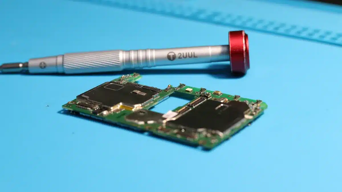
Visual Inspection
Start with a visual inspection. This step is very important for spotting visible damage. Look for these signs:
Burn Marks or Scorching: Dark brown or black spots show overheating or short circuits.
Bloated or Leaking Capacitors: Check for rounded tops or leaks at the base of capacitors.
Corrosion or Rust: Green or white powdery buildup often shows on solder joints.
These signs help you find problems before they get worse. Other common issues include:
Overheating parts
Moisture and rust
Electric overload
Solder joint failures
Electrical Failures
Electrical failures can cause big problems in circuit boards. You might see signs like:
Overheating parts
Strange noises, like buzzing or sizzling
Burning smells
Visible damage, like cracks or melted parts
Frequent circuit breaker trips
Common causes of electrical failures are:
Component Failures: Poor quality or wrong specifications can cause issues.
Faulty Traces: Physical damage or rust can stop electrical flow.
Power Failures: Low voltage supply often leads to device problems.
Design Errors: Mistakes in placing parts can create issues.
By spotting these signs and causes, you can start fixing circuit board problems effectively.
Tools for Circuit Board Repair
When you fix circuit boards, having the right tools is very important. Good tools make your work easier. They also help you diagnose and repair better. Here are some key tools for circuit board repair:
Multimeters and Oscilloscopes
Multimeters and oscilloscopes are crucial for finding circuit board problems.
Multimeter: This tool checks basic electrical properties like voltage, current, and resistance. It helps you quickly find issues like open or short circuits.
Oscilloscope: This device shows a graph of how an electronic signal changes over time. It helps you look at signal details like amplitude and frequency.
Using both tools together gives you a full view of circuit board performance. For example, a multimeter gives exact measurements. An oscilloscope shows quick changes in signals. This mix helps you find and fix problems better.
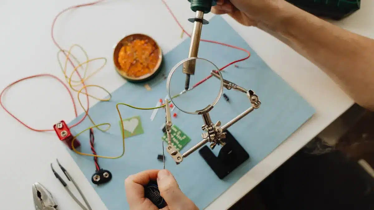
Soldering Techniques for Circuit Board Repair
Soldering is a key skill for fixing circuit boards. Different soldering methods make sure connections between parts are strong. Here are some good soldering techniques:
Hand Soldering: This method is great for prototypes and repairs. It lets you work on single parts carefully.
Surface Mount Technology (SMT): SMT is used for making many boards at once. It allows more parts to fit on circuit boards.
Through Hole Technology: This method is good for parts that need strong connections.
To make good solder joints, follow these tips:
Use high-quality soldering tools and materials.
Clean surfaces to remove dirt before soldering.
Put solder on the tip of the soldering iron for better heat flow.
Heat both the board and part lead before adding solder to the joint.
Let the joint cool without moving it for a strong connection.
Following these soldering tips will help you create strong and reliable connections on your circuit boards.
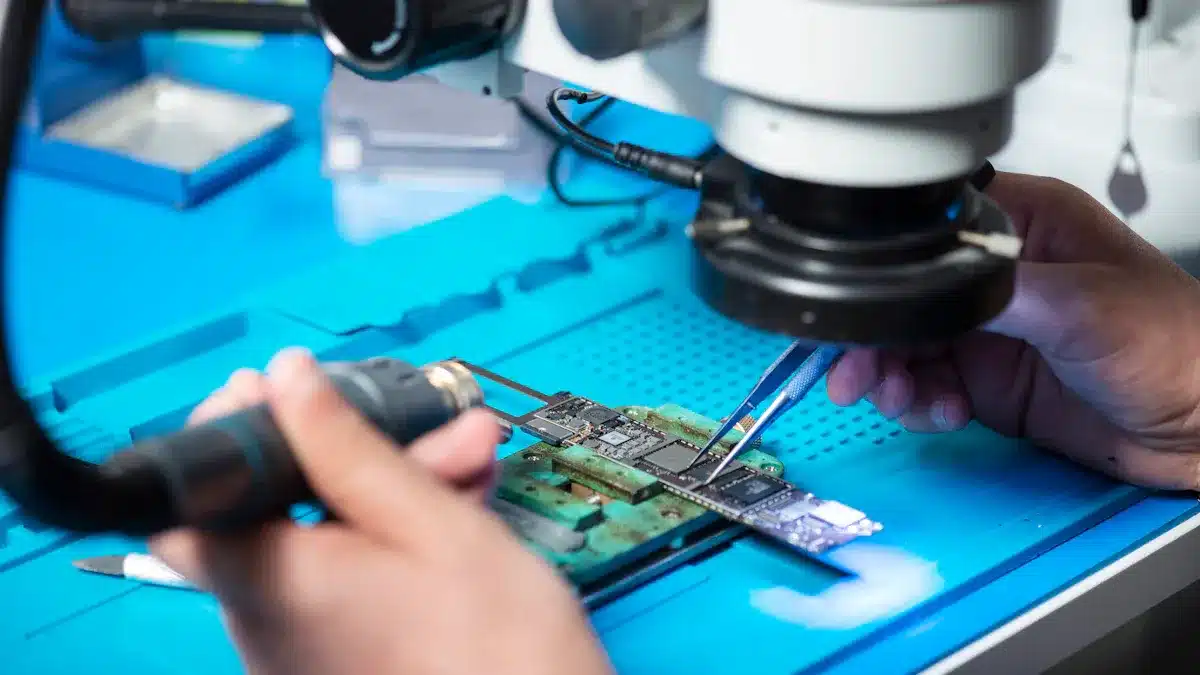
Besides these tools, think about using a PCB inspection jig or magnifier, thermal camera, and logic analyzer for better diagnostics. Good diagnostic tools can help find problems and test repairs. For example, automated optical inspection can lower defect rates by up to 40% in consumer electronics.
Getting proper training, like IPC-7711/7721 courses, can also improve your skills in circuit board repair.
Step-by-Step Repair Process
When you have circuit board problems, using a clear plan helps you fix them well. Here’s a simple step-by-step repair process to help you.
Isolating Problem Areas
Before you start fixing, you need to find the problem areas on the circuit board. This step is very important for spotting the exact issues. Here are some good ways to help you:
Visual Inspections: Look for clear signs of damage, like burned parts or broken lines.
Physical Inspections: Feel for hot spots that might mean overheating or broken parts.
Component Testing: Use a multimeter to check each part for problems. This helps you see which parts need to be replaced.
By finding the problem areas, you can focus your repairs where they matter most. For example, if you see a bad resistor, you will know where to work.
Repairing Damaged Printed Circuit Board Pads
After you find the problem areas, you might need to fix damaged printed circuit board pads. This step needs careful work to avoid more damage. Here are some good tips for fixing damaged pads:
Tidy Up the Damaged Track: Remove as little damage as you can. Use a sharp knife to cut carefully through the damaged tracks.
Exposing the Track: Scrape off some of the solder resist with a knife or fine sandpaper. Make sure the exposed track is clean and shiny.
Sticking Copper Tape Over the Exposed Track: Put copper tape on top, overlapping the existing track a bit.
Soldering the Copper Tape Joints: Carefully solder the joints where you made the repair, using low heat.
Pierce to Make the Hole: Rub over the pad area with a hard, rounded item to push the copper tape down over the pad area.
Solder in Your Component: Fit and solder the component as usual, keeping heat input short.
Carefully Trim the Repair: Trim the extra copper tape carefully, as the repair is weaker than the original track.
For example, if you find a lifted pad, you can use epoxy to press it back down. Or, a jump wire repair can create a new connection if a pad is completely gone. These methods help keep your circuit board working after repairs.
By following this step-by-step repair process, you can fix circuit board issues well and improve your skills in circuit board repairing.
Troubleshooting Tips
Testing After Repairs
After you finish fixing your circuit board, you need to test it. This checks if it works right. Here are some good ways to test and check:
Perform performance testing: Test how the board works in different conditions.
Conduct environmental testing: Check how the board works in different temperatures and humidity.
Verify compliance: Make sure the board follows safety and EMC rules.
Perform quality control checks: Look at the board closely to find any problems.
You can also use these methods to check your repairs:
Visual inspection: Look for any scratches or breaks.
Continuity testing: Use a multimeter to check if paths on the board work.
Cross-probing: Use software to match diagrams with parts on the board.
These steps help you make sure your circuit board repairs worked and that it is ready to use.
Preventative Measures
To stop future circuit board problems, think about these preventative measures:
Conduct failure analysis: Find out what caused past failures. This can help you avoid them again.
Use conformal coating: Protect your PCBs from dust and moisture. Acrylic resins and epoxies work well.
Test during assembly: Check reliability before you sell the product. In-circuit testing and automated optical inspection are helpful.
Design for reliability: Use good thermal management and quality parts. Proper assembly is key for lasting performance.
Control environmental factors: Use high-quality solder and inspect carefully to avoid defects.
By following these tips, you can greatly lower the chances of having circuit board failures later.
To sum up, you can find and fix circuit board problems by doing these important steps:
Look at Visual Elements
Check Physical Parts
Test Each Component
Test Integrated Circuits
Check The Power Supply
Compare a Broken Circuit Board With a Working One
Use Signal Probing
As you get better, think about using tools like repair kits and online guides to learn more. Always remember that safety is very important. Make sure your workspace is ready, check the board, and be careful with the parts. Being precise in your repairs will help you get better results and make your printed circuit boards last longer.
FAQ
What tools do I need for circuit board repair?
You need a multimeter, soldering iron, solder, and a magnifying glass. These tools help you find problems and fix them well.
How can I prevent circuit board damage?
To stop damage, keep your circuit boards dry. Avoid overheating and use good parts. Regular checks also help find problems early.
What should I do if I find a burnt component?
If you see a burnt part, replace it right away. Use a multimeter to check for other issues before putting in a new part.
How do I know if my repair was successful?
Test the circuit board after you fix it. Check if it works right and look for signs of overheating or strange behavior.
Can I repair a circuit board myself?
Yes, you can fix a circuit board by yourself. With the right tools, knowledge, and patience, you can find and fix many problems.
See Also
Proven Strategies for Analyzing PCBA Failures Effectively
Innovative Testing Approaches for PCBA in Electronics Production
Understanding the Hard Reset Procedure for PCBA Devices
Key Considerations for Selecting the Ideal PCBA Main Board
Understanding In-Circuit Testing for PCBA and Its Importance