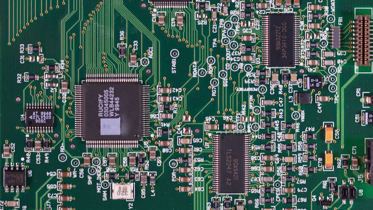
Printed circuit boards (PCBs) are key parts of long-life industrial automation PCB manufacturing systems. They help different parts communicate smoothly, ensuring that these systems operate efficiently. Good designs make these systems last longer and work better. For instance, Rigid-Flex PCBs handle fast signals without losing quality, making them great for new tech like 5G and IoT. They are strong and perform well in tough conditions. Predictive analytics also contribute by preventing sudden breakdowns and reducing repair costs. By focusing on robust PCB designs, engineers create systems that function effectively and endure longer with fewer issues.
Key Takeaways
Use strong materials for PCBs to make them last longer.
Control heat well to stop damage and make PCBs work longer.
Test and check carefully to find and fix problems early.
Make PCBs easy to upgrade and fix as technology changes.
Follow rules and get certifications to make better products and gain trust.
Importance of PCB Design in Industrial Automation

Role of PCBs in Industrial Automation Systems
PCBs are the main part of automation systems. They link and support electronic parts, helping them work together. In factories, PCBs must handle fast signals, power, and data well. For example, high Tg PCBs are used in motor drives and telecom. These PCBs last longer and work better in tough conditions. This reduces downtime and makes customers happier.
Case Study | Description |
|---|---|
Medical Device | High Tg PCBs made devices smaller and added wireless features. |
Industrial Equipment | Improved motor drives that work in high heat. |
Telecommunications | Better signals and less noise in routers for good performance. |
Why PCB Design Impacts System Reliability and Longevity
PCB design affects how long and well systems work. A good PCB design stops failures by managing heat, signals, and protection. For example, improving high-speed boards can cut design time by 45% and boost signal quality by 30%. These changes make systems work better, cost less to fix, and last longer.
Case Study | Key Metrics |
|---|---|
High-Speed Communication Board | |
Consumer Electronics Miniaturization | 60% quicker part placement, 40% fewer heat problems. |
Challenges in Industrial Environments for PCB Durability
Factories have tough conditions that can harm PCBs. Heat, moisture, and stress are common problems. For example, temperature tests check if PCBs handle heat changes. Vibration tests see if they stay strong under shaking. Fixing these issues in design helps PCBs work well in harsh places.
Challenge | Description |
|---|---|
Rules to lower human contact with PCBs. | |
Temperature Effects | High heat can hurt PCB performance. |
Humidity Effects | Moisture can cause rust and failures. |
Mechanical Stress | Shaking can damage solder and parts. |
Temperature Cycling: Checks if PCBs survive heat changes.
Humidity Testing: Tests resistance to water and rust.
Vibration Testing: Checks strength during shaking.
Key Factors in PCB Design for Longevity
Picking the Right Materials for Durable PCBs
Choosing good materials is key to making strong PCBs. The materials affect how well the PCB works and how long it lasts. Engineers must pick materials that fit the needs of industrial PCBs. For example, high Tg laminates are great for handling heat. Low dielectric constant materials help signals stay clear in fast designs.
The properties of materials decide how long a PCB will last. Peel strength keeps the PCB strong. Glass transition temperature (Tg) and thermal decomposition temperature (Td) help with heat resistance. Electrical properties like dielectric constant and flame retardancy improve safety. Water absorption and CAF resistance protect against moisture and damage.
Metric Type | |
|---|---|
Physical Properties | Peel strength, Coefficient of thermal expansion (CTE) |
Chemical Properties | Glass transition temperature (Tg), Thermal decomposition temperature (Td) |
Electrical Properties | Dielectric constant, Dielectric loss, Flame retardancy |
Environmental Performance | Water absorption, CAF resistance, Comparative tracking index (CTI) |
Reliability Factors | Copper foil peeling strength, Impact of moisture on dielectric constant and thermal expansion |
Using materials that meet these needs helps PCBs last longer. It also lowers the chance of failure in tough environments.
Managing Heat for Better PCB Performance
Controlling heat is very important for reliable PCBs. Heat causes over half of all electrical failures. Good heat control stops damage and keeps systems working well.
There are many ways to manage heat in PCBs. Engineers use heat sinks, thermal vias, and copper planes to move heat away. Placing parts in the right spots avoids hot areas. Special materials help transfer heat better. Studies show that a 10 °C rise in heat can cut system life by half. By managing heat well, PCBs last longer and need fewer repairs.
Heat causes over 55% of electrical failures.
Good heat control makes systems last longer.
A 10 °C rise in heat can cut system life by 50%.
Protecting PCBs from Harsh Conditions
Factories can be tough places for PCBs. Moisture, dust, and shaking can cause problems. Protecting PCBs from these things is important for keeping them working.
Engineers use coatings and coverings to keep out moisture and dirt. Designs that resist shaking stop parts from breaking. Strong soldering materials keep joints from failing under stress. Tests like CAF resistance and water absorption check if PCBs can handle wet and rusty conditions.
By focusing on protection, PCBs can work better and last longer in hard environments.
Keeping Signals Clear and Reducing Noise
Clear signals and less noise are very important for a PCB to work well in industrial systems. Bad signals can cause errors, system problems, and shorten the PCB’s life. Engineers must focus on keeping signals clear and cutting down interference to make systems last longer and work better.
Ways to Keep Signals Clear and Reduce Noise
There are many ways to improve signals and reduce noise in PCBs. A good stack-up design keeps signals strong and reduces loss. Arranging layers properly gives signals a steady path, avoiding problems. Ground planes block interference and stop ground bounce, which can mess up signals. A balanced layout stops the PCB from bending during production, keeping it reliable.
Method | How It Helps the PCB Work Better |
|---|---|
Good Stack-up Design | Keeps signals strong and clear. |
Cutting Crosstalk | Lowers interference and signal mixing. |
Layer Arrangement | Gives signals a steady path to travel. |
Ground Planes | Blocks interference and stops signal problems. |
Balanced Layout | Stops bending during production. |
Heat and Signal Quality
Managing heat is key to keeping signals clear. Too much heat can harm materials and mess up signals. Engineers use thermal vias and copper planes to move heat away. This stops hot spots that could hurt signal quality. By controlling heat, PCBs work well even in hot places.
Why Clear Signals and Less Noise Matter
Using these methods has big benefits. Systems have fewer errors, making them more reliable. Better signals mean less fixing is needed, saving money. Strong signal quality also helps PCBs handle fast data, which is important for modern systems.
Tip: Engineers should test PCB designs with special tools to find signal problems early. Fixing issues before production makes systems more reliable.
By focusing on clear signals and less noise, engineers can make PCBs that work well in tough factory conditions. These steps help PCBs last longer and make automation systems more efficient.
Common Design Mistakes to Avoid
Bad Component Placement and Trace Routing
Placing parts and traces poorly can hurt how a PCB works. Bad placement makes traces longer, causing signal problems and delays. Poor routing can make layouts messy, leading to noise and interference. For example:
Parts near the board edge can break during handling.
Not enough space between parts can cause soldering problems.
Straight-line routing may not stop crosstalk in fast designs.
To fix these issues, engineers should keep traces short and clear. They must also leave enough space and use good grounding to avoid errors.
Skipping Testing and Validation
Not testing designs well can make PCBs less reliable. Skipping prototypes can lead to costly fixes and delays later. Testing helps find and fix problems early, making production smoother. Studies show testing early improves safety and quality.
Engineers working with high voltage must follow safety rules. By testing prototypes and running checks, they can lower risks and make better PCBs.
Ignoring Environmental Protection
Not protecting PCBs from the environment can cause failures. Factories have moisture, dust, and heat that can damage PCBs. Coatings and covers help protect parts from these dangers.
Research shows poor protection can harm both PCBs and people. For example, bad materials can pollute indoor air. Using coatings and better ventilation can solve these problems. Engineers should focus on protection to make PCBs last longer and stay safe in tough places.
Using Low-Quality Materials or Components
Using bad materials or parts in PCB making can cause problems. Weak materials cannot handle tough factory conditions like heat, water, or stress. This makes machines break often, costs more to fix, and lowers how well they work.
Good materials make PCBs last longer and work better. Cheap materials can cause more trash and break rules about the environment. Breaking these rules can lead to fines or other problems for companies. Engineers should pick materials that handle heat and stress well to keep systems working for a long time.
Parts used in PCBs also do not last as long now. Picking bad parts can make them fail early, causing big problems. For example, parts that cannot handle heat may stop working fast, breaking the whole system.
To stop these issues, factories need to check quality during design and making. Testing can find bad materials or parts before they are used. Using strong materials and good parts helps PCBs last longer, work better, and follow industry rules.
Tip: Always check if materials and parts can handle heat and stress for factory systems.
Best Practices for Long-Lasting PCBs

Testing and Quality Checks for Reliable PCBs
Testing is important to make sure PCBs work well. Engineers use different tests to find problems early. Functional tests check if the PCB works as planned. Stress tests see if it can handle heat and pressure. These tests help improve weak areas so PCBs can survive tough factory conditions.
Quality checks during making PCBs are also very important. For example:
Fixing problems early saves money on repairs and returns.
Happy customers trust products that always meet high standards.
Heat stress causes over half of electronic failures. This shows why good heat design and testing are needed. By doing strong tests and checks, engineers can make PCBs that last long and work well in factories.
Picking Strong and Reliable Parts
Good parts make PCBs last longer and work better. Engineers test parts to see how they handle stress. These tests show weak spots and help improve designs for hard jobs.
Using strong parts also makes PCBs perform better. Testing ensures parts meet quality rules, which helps them last. For example:
Good capacitors and resistors work well even in heat changes.
Advanced chips keep signals clear and reduce noise.
Strong connectors and soldering stop breaks from shaking.
Careful checks during assembly make sure all parts are good. Engineers pick parts that fit factory needs. This lowers repair costs and keeps PCBs working longer.
Making PCBs Easy to Upgrade and Fix
PCBs should be easy to upgrade and repair. A good design lets engineers add new features later. This keeps the PCB useful as technology changes. For example, modular designs allow adding parts without big changes.
Easy repairs are also important. Engineers label parts clearly and use standard connectors. This makes fixing problems faster and reduces downtime.
Engineers also use tools to test how PCBs will work in different situations. This helps improve designs before making them. By focusing on upgrades and repairs, engineers create PCBs that last longer and stay useful in factories.
Adhering to Industry Standards and Certifications
Following industry standards and certifications helps ensure PCB designs are safe, reliable, and high-quality. These rules provide clear steps for making and checking PCBs, reducing mistakes and improving how they work. By using these guidelines, engineers can create PCBs that work well in tough industrial settings.
Key Industry Standards and Certifications
Many important standards guide how PCBs are made and tested. These certifications make sure products are safe, strong, and work properly:
ISO: Focuses on making processes better and controlling quality.
IEC: Sets global rules for electrical safety and performance.
UL: Checks if products follow electrical safety rules.
MIL-PRF: Lists rules for military electronics to stay strong and reliable.
MIL-STD: Covers general rules for military hardware.
Each certification looks at different parts of PCB design. This ensures PCBs meet the needs of industries like electronics and military systems.
Benefits of Adhering to Standards
Following standards has many benefits for engineers and manufacturers. These advantages go beyond just following rules and help improve products and careers:
Better Reputation: Certifications show skill and build trust with clients.
Fewer Mistakes: Using standard methods lowers errors and saves money.
Stronger Products: Certified PCBs last longer and handle stress better.
Career Growth: Certified engineers get better jobs and pay.
Client Confidence: Certifications prove a focus on safety and quality.
For example, PCBs certified under UL rules are safer and less likely to fail. ISO-certified PCBs are made consistently, making them more reliable.
Role of Certifications in Inspection Processes
Certifications are important for checking PCBs during production. They set clear rules for automated inspection systems, helping find problems faster. For example, optical inspection tools use these standards to spot defects like bad soldering or misaligned parts. This makes inspections quicker and more accurate.
Using certifications also reduces human mistakes. Automated systems follow these rules to catch issues early. This improves product quality and lowers costs compared to manual checks.
Promoting a Standardized Approach
Certifications help keep PCB design and manufacturing consistent. This makes sure products meet industry needs no matter where they are made. Standardized methods also make teamwork easier since everyone follows the same rules.
For instance, a designer using IEC rules can work easily with a factory using the same standards. This reduces confusion and speeds up production. Standard practices also help factories make more PCBs without losing quality.
Tip: Engineers should learn about new certifications to stay competitive. Keeping up with changes ensures designs meet new rules and technology needs.
By following industry standards and certifications, engineers and manufacturers can make better PCBs. These practices improve product quality, build trust with clients, and lead to success in industrial automation.
Making a strong PCB is key for reliable factory systems. Engineers should focus on picking good materials, managing heat, and testing well. Materials like High-Tg FR-4 and polyimide handle heat better and last longer. Ceramic laminates work great for fast signals in high-tech uses. Controlling heat stops parts from getting too hot and breaking. Tests that expose PCBs to heat and shaking find weak spots early. By using these steps, engineers can lower breakdowns, make systems work better, and keep them running longer in factories.
FAQ
What matters most for making long-lasting PCBs?
Choosing the right materials is very important. Strong materials make PCBs last longer and work better, especially in factories. Engineers should pick materials that handle heat, water, and stress well.
How does controlling heat help PCBs work better?
Good heat control stops parts from getting too hot. Overheating can break parts. Using things like heat sinks, thermal vias, and copper layers moves heat away. This keeps PCBs working longer.
Why is keeping signals clear important for PCBs?
Clear signals mean data moves without mistakes. Bad signals can cause errors and system problems. Engineers arrange layers and use ground planes to keep signals strong and clear.
How does smart PCB making improve reliability?
Smart PCB making uses new tools like automatic testing and checks. These tools catch mistakes early, save time, and make sure PCBs are made well every time.
What tests check if PCBs are strong?
Important tests include heat cycling, shaking tests, and water resistance checks. These tests copy tough factory conditions to find and fix weak spots in PCBs.
See Also
Why PCBA Manufacturing Skills Matter in Electronics Development
Selecting the Ideal PCBA Manufacturer for Your Specific Needs
Essential Advice for Picking the Perfect Main PCBA