
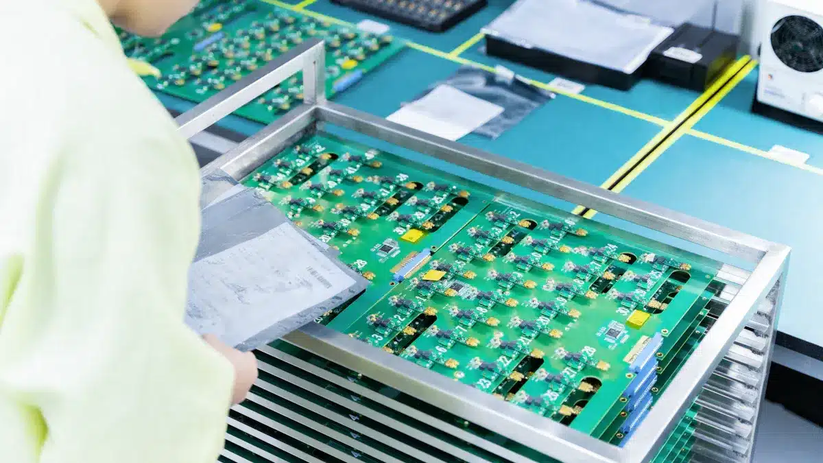
The PCB assembly process involves placing various electronic components onto a printed circuit board (PCB). This process is crucial for producing reliable and functional electronic devices. Understanding PCB assembly is essential for manufacturers, as it directly impacts the quality of the final product. Recent studies have concentrated on methods to prevent issues during the assembly of PCB assy. For instance, enhancing critical factors such as solder paste printing significantly improves product reliability and quality.
Aspect | Evidence Summary | Impact on Reliability and Quality |
|---|---|---|
Failure Prevention Methods | Current methods (SPI, AOI, ICT) respond to issues, leading to waste and rework. | Highlights the necessity for improved process control to enhance yield and reduce defects. |
Intelligent Assembly Process Improvement System (IAPIS) | Integrates k-means clustering and the multi-response Taguchi method to identify key factors and optimize settings. | Facilitates better optimization of solder paste printing and other assembly steps, increasing yield and product quality. |
Key Takeaways
The PCB assembly process puts electronic parts on a board. This helps devices work better and last longer.
Applying solder paste correctly and placing parts accurately is very important. This helps avoid mistakes and keeps quality high.
Quality control methods like Automated Optical Inspection and In-Circuit Testing find problems early. This helps save money.
Automated assembly is fast and consistent for big production. Manual assembly works better for small runs and complex designs.
Picking the right soldering method and design software makes things more efficient. It also improves the final product’s reliability.
Basics of PCB Design
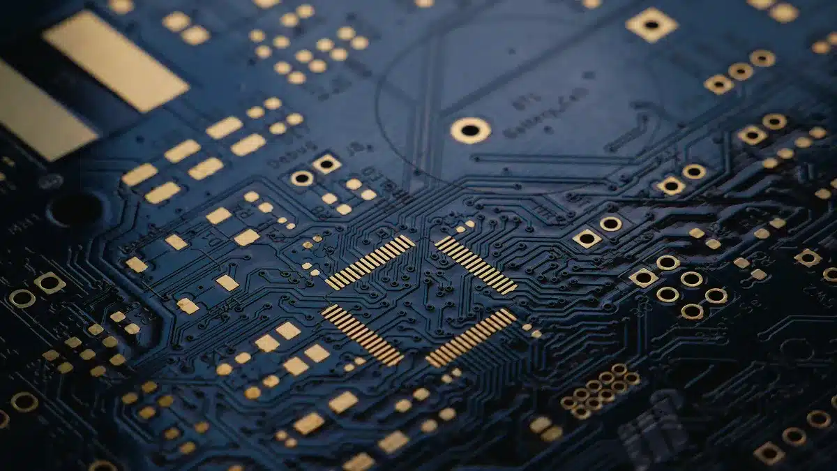
Components of a PCB
A printed circuit board (PCB) has many parts. Each part is important for how the circuit works. Knowing these parts helps understand why they matter in design and performance. Here are some common parts found on a PCB and what they do:
Component | Function |
|---|---|
Resistors | Limit the flow of electrical current |
Capacitors | Store and release electrical energy, keep voltage steady |
Diodes | Let current flow one way, protect against reverse currents |
Transistors | Boost or switch electrical signals |
Inductors | Store energy in magnetic fields, resist quick changes in current |
Transformers | Move electrical energy between circuits, change voltage levels |
Integrated Circuits (ICs) | Carry out complex tasks by combining many parts on a chip |
Relays | Use small signals to control larger currents, provide safety isolation |
Connectors | Create electrical links between circuit parts or outside devices |
Sensors | Detect changes in the environment and turn them into electrical signals |
These parts work together to make sure the PCB functions well. The features of each part can greatly affect how the assembly goes and how well the product works. For example, the size and shape of parts can change how efficiently they are assembled and how much it costs.
Design Software
Making a PCB needs special software tools. These tools help create schematics and layouts. There are many software options, each with different features for different users. Here is a comparison of some popular PCB design software:
Software Tool | Key Features | Best For |
|---|---|---|
Altium Designer | 3D views, large component libraries, supply chain links, teamwork tools | Professional PCB designers |
EAGLE | Easy to use, schematic and layout editors, big component library | Beginners and mid-level designers |
KiCad | Free to use, 3D viewer, large library, strong community support | Hobbyists, students, budget-friendly designers |
OrCAD | Very precise, simulation, signal quality checks, many tools | Advanced engineers, industry pros |
Proteus | Circuit simulation, easy to use, prototyping tools | Teachers, students, prototyping designers |
These tools make the design process better. They let designers see and test their circuits before making them. The right software can make the design process smoother and improve the PCB’s overall quality.
PCB Assembly Steps
The PCB assembly process has several important steps. These steps help put electronic parts onto a printed circuit board (PCB) correctly. Each step is important for the quality and reliability of the final product. Here are the main steps in the PCB assembly process:
Solder Paste Application
Solder paste application is the first step in the PCB assembly process. This step means putting solder paste carefully onto the PCB pads using stencils. It is very important to do this accurately. If there is too little or too much solder, it can cause problems like solder bridges or weak solder joints. Common issues during this step include:
Stencil not lined up correctly
Solder paste slumping or bleeding out
Uneven paste thickness
To fix these problems, manufacturers often improve stencil design and use automated solder paste inspection (SPI). This helps make sure the application is even. Good solder paste printing is very important. It helps with placing components correctly.
Component Placement
After applying solder paste, the next step is component placement. Automated pick-and-place machines do this job quickly and accurately. These machines can place between 25,000 and 120,000 components each hour, depending on the type. The accuracy of placement is often better than ±0.025mm. This is very important for tiny parts like 01005 packages.
Advanced vision systems help monitor and fix placement mistakes in real-time. This reduces defects by about 42%. Accurate component placements are very important. Even small mistakes can cause big problems, like misaligned parts or bad electrical connections.
Soldering Techniques
Once the components are placed, the next step is soldering. The two main soldering methods used in PCB assembly are reflow soldering and wave soldering.
Factor | Reflow Soldering | Wave Soldering |
|---|---|---|
Complexity | Simpler process; easier to control conditions | More complex; needs skill and careful handling |
Speed | Slower because of solder paste and oven time | Faster; PCBs move quickly over solder wave |
Usage | Best for surface-mount devices | Best for through-hole components |
Reflow soldering heats the PCB in a reflow oven. The solder paste melts and hardens, holding the components in place. This method works well for surface-mount technology (SMT) and dense boards. Wave soldering is usually for through-hole components. It is faster but may have more defects.
Testing and Inspection
The last step in the PCB assembly process is testing and inspection. This step checks if the assembled PCB works correctly and meets quality standards. Different testing methods are used, including:
Automated Optical Inspection (AOI): Finds visual problems like solder gaps and misaligned parts.
In-Circuit Testing (ICT): Tests electrical properties at certain points on the PCB.
Functional Testing: Checks how the PCB works under simulated conditions.
Each of these methods is very important. They help find defects early in production, making sure only good products are sold.
Accurate assembly drawings are very important during the PCB assembly process. They give clear coordinates and directions for placing components. This reduces the chance of misalignment and failures. Wrong drawings can cause expensive reworks and delays. This shows how important precision is in the design phase.
Importance of Quality Control in PCB Assembly
Quality control is very important in the PCB assembly process. It makes sure that each printed circuit board works well and meets industry standards. When manufacturers use good quality control methods, they can improve how well electronic devices perform.
Ensuring Reliability
Quality control helps find and fix problems early in the assembly process. This way, it stops early failures, which can make electronic devices last longer. Here are some key ways quality control helps with reliability:
Adherence to Standards: Quality control makes sure that products follow industry standards, like IPC-A-610. This helps with getting certified and accepted in the market.
Defect Detection: Methods like Automated Optical Inspection (AOI) and burn-in testing find problems before they reach customers.
Consistent Manufacturing: Using standard processes lowers differences, which makes the final product more reliable.
Cost Reduction: Good quality control cuts down on rework, waste, and warranty claims, which lowers production costs.
By focusing on these areas, manufacturers can make PCBs that work reliably over time, meeting what users expect.
Reducing Defects
Defects in PCB assembly can cause big problems for both manufacturers and users. Common defects include solder bridging, not enough solder, and parts being out of place. These issues can lead to electrical shorts, weak connections, and even total device failures. The results of poor quality control can be serious:
For manufacturers, defects mean more production mistakes, higher costs, and possible damage to their reputation.
For users, defects lead to unreliable performance and shorter product life.
To tackle these problems, manufacturers can use several strategies to lower defects during the PCB assembly process:
Design for Manufacturability (DFM): This method makes designs simpler to reduce assembly mistakes.
Soldering Process Optimization: Matching soldering temperatures to materials and using multi-zone reflow ovens can improve solder quality.
Early Defect Detection: Using AOI can find defects with over 95% accuracy.
Comprehensive Testing: Methods like In-Circuit Testing (ICT) and functional testing help ensure that each PCB meets performance standards.
By focusing on these strategies, manufacturers can greatly reduce defects, leading to better quality products and happier customers.
Comparing PCB Assembly Methods
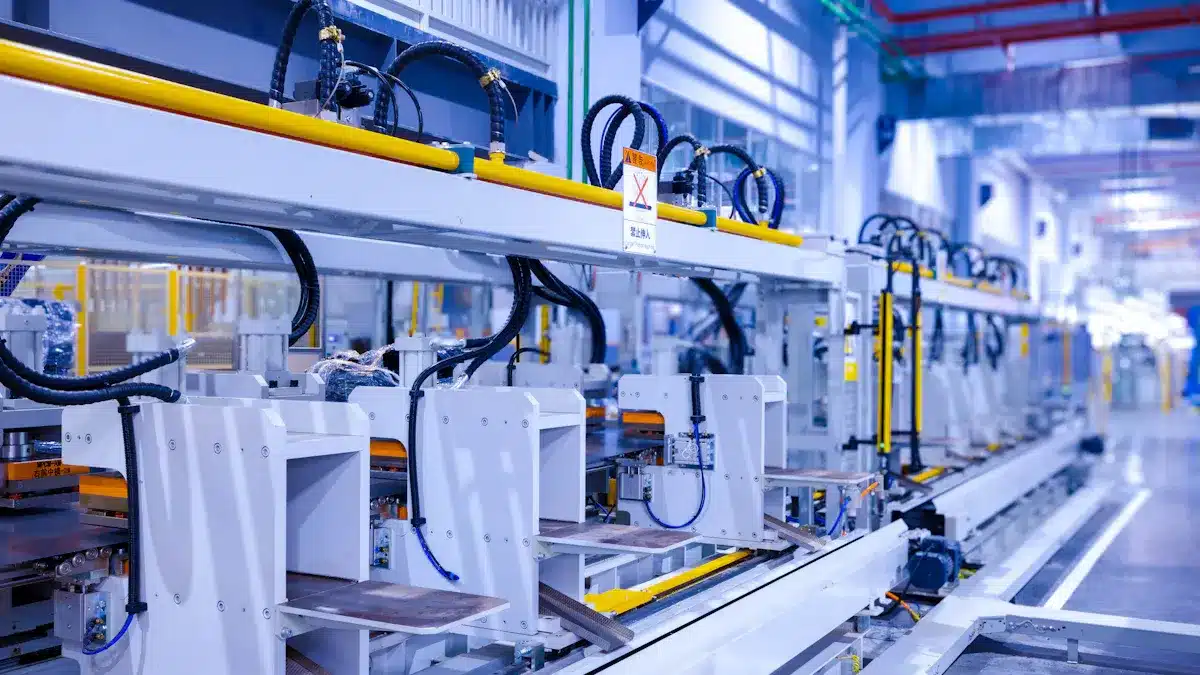
Manual vs. Automated Assembly
Choosing between manual and automated assembly methods is very important for the PCB assembly process. Each method has good and bad points.
Aspect | Manual Assembly | Automated Assembly |
|---|---|---|
Process | Skilled workers place and solder parts by hand | Machines place and solder parts automatically |
Speed | Slower and needs more workers | Fast production |
Flexibility | High; can change designs easily | Low; not easy to change designs |
Quality Control | Based on skill; can check visually | Consistent and precise; fewer mistakes from people |
Cost | High setup cost; cheaper for large amounts | |
Maintenance | Simpler to maintain | Needs skilled help for maintenance and fixing |
Suitability | Good for low amounts, prototypes, or complex designs | Good for high amounts, steady, and precise production |
Automated assembly is better for speed, consistency, and fewer mistakes, especially when making a lot of items. However, manual assembly is still needed for small runs, prototypes, or when parts are hard to place or solder automatically.
SMT vs. Through-Hole Technology
Surface mount technology (SMT) and through-hole technology (THT) have different uses in PCB assembly. Each has special benefits.
Advantage Aspect | Surface Mount Technology (SMT) Benefits |
|---|---|
Assembly Speed | Faster production because of solder paste and reflow soldering, no need to drill holes. |
Component Density | Smaller parts allow more components on PCBs, letting placement on both sides of the board. |
Application/Requirement | Reason for Preferring Through-Hole Technology (THT) |
|---|---|
Aerospace, Military, Automotive | Strong connections that can handle physical stress, vibrations, and tough conditions. |
High-Power and High-Voltage Circuits |
The surface mount process allows for more parts and faster assembly. On the other hand, the through-hole process gives strong connections, making it good for tough situations.
The PCB assembly process is very important in the electronics world. It makes sure that printed circuit boards work well and meet quality rules. Here are some key parts:
Automated Optical Inspection (AOI) finds problems like parts that are not lined up.
X-Ray Inspection looks for hidden problems in solder joints.
In-Circuit Testing (ICT) checks if the parts work electrically.
Functional Testing tests how the board works in real-life situations.
These methods improve product reliability and make customers happy. As technology gets better, PCB design and assembly become more complex. Knowing this process helps us see why it is important for making good electronic devices.
FAQ
What is PCB assembly?
PCB assembly is when electronic parts are put onto a printed circuit board. This process makes sure the parts connect correctly. This allows the board to work properly in electronic devices.
Why is quality control important in PCB assembly?
Quality control makes sure each PCB meets industry rules. It helps find problems early, which improves reliability. This also lowers costs from rework and warranty claims.
What are the main types of soldering techniques?
The two main soldering methods are reflow soldering and wave soldering. Reflow soldering works best for surface-mount devices. Wave soldering is usually used for through-hole parts.
How does automated assembly differ from manual assembly?
Automated assembly uses machines to place and solder parts. This offers speed and accuracy. Manual assembly depends on skilled workers. It gives flexibility but is often slower.
What role does design software play in PCB assembly?
Design software helps engineers make schematics and layouts for PCBs. It allows for testing and simulation before making them. This ensures better designs and fewer mistakes during assembly.
See Also
A Comprehensive Guide To PCBA Production And Assembly
Exploring Turnkey PCB Assembly And Its Key Benefits
Why PCBA Manufacturing Skills Are Vital For Electronics Design
An Overview Of PCBA Services And Their Manufacturing Role
Understanding PCBA In Electronics And Its Critical Importance