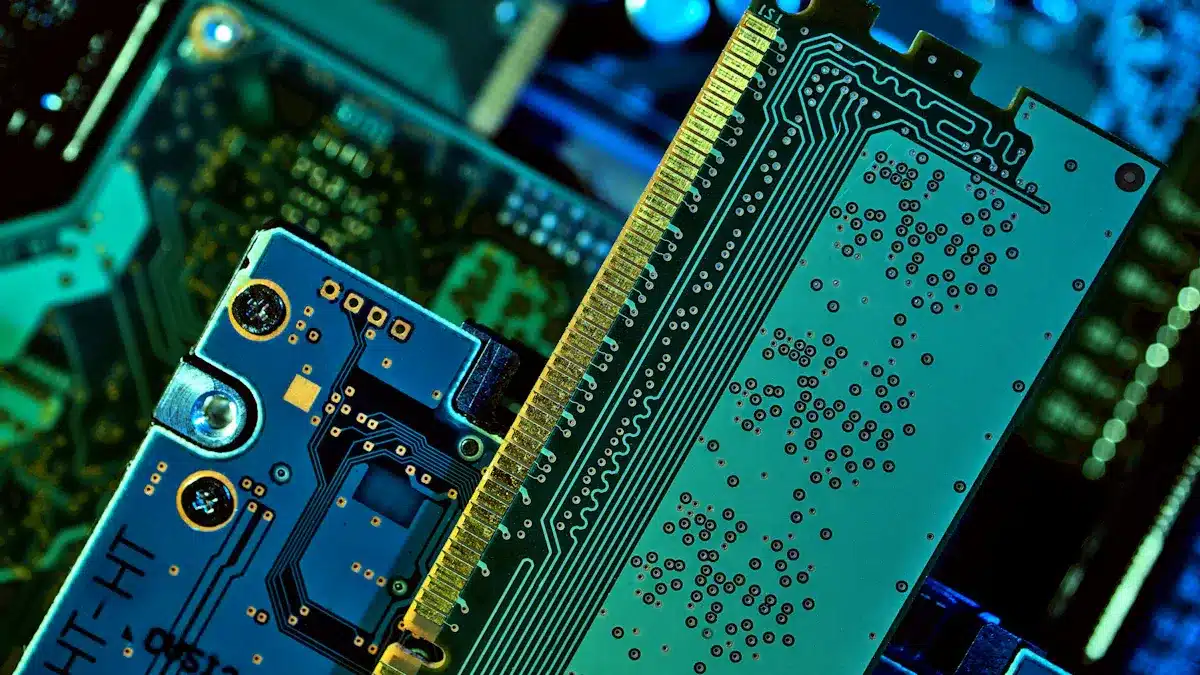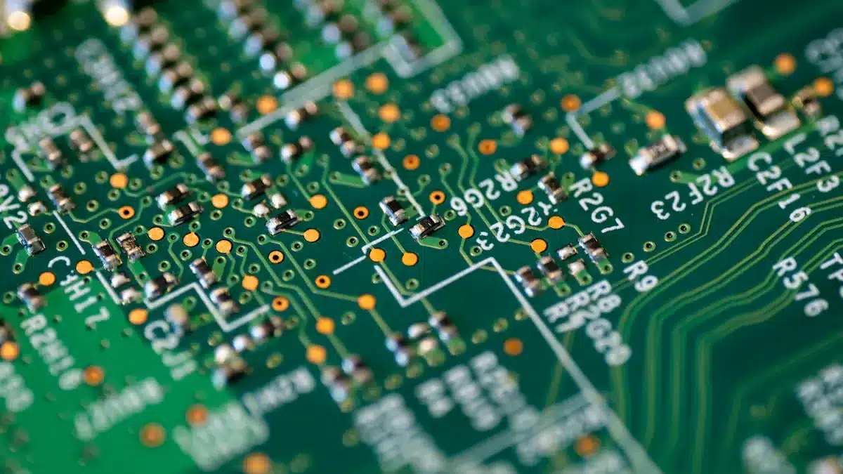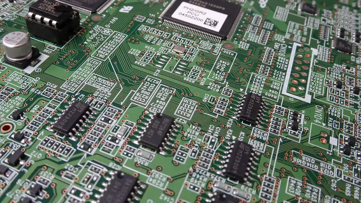
Printed circuit boards (PCBs), which stand for “printed circuit boards,” are important parts of today’s electronic devices. They act like a backbone, connecting different electronic parts to create a working system. The name PCB shows how it helps with electrical connections using printed paths. As technology improves, the worldwide PCB market has grown significantly. It was worth $75 billion in 2021 and is expected to reach $120 billion by 2030. This growth indicates that more people want PCBs for consumer electronics and cars.
Key Takeaways
Printed circuit boards (PCBs) link electronic parts. This helps devices work better.
There are three main types of PCBs: single-sided, double-sided, and multilayer. Each type has different uses.
PCBs make electronic devices smaller. They also improve how well they work and how reliable they are.
To understand how PCBs work, you need to know about their layers. These include the substrate and conductive layers.
Picking the right type of PCB depends on how complex your project is and what it needs.
Definition of PCBs
What is a Printed Circuit Board?
A printed circuit board (PCB) is a flat board made from materials that do not conduct electricity. It connects electronic parts together. The word “printed” means how the paths for electricity are made on the board. This technology started in the early 1900s. Charles Ducas printed circuit designs on non-conductive materials in 1925. Paul Eisler improved this technology in 1941 by using copper foil on a non-conductive base. This led to the first modern PCB.
Here are some key points about the history of PCBs:
PCB stands for “Printed Circuit Board.”
The idea started in the early 1900s.
Charles Ducas’s work helped create modern PCBs.
Paul Eisler made the first practical double-sided PCB in 1942.
Purpose of PCBs
PCBs are very important in today’s electronics. They have many roles that improve how electronic devices work. Here are the main jobs of printed circuit boards:
Connection: PCBs link different electronic parts to make a complete circuit. This connection helps devices work as planned.
Support: They give strong support to electronic parts. This support keeps parts safe from outside interference and makes the circuit system more reliable.
Heat Dissipation: PCBs help get rid of heat from electronic parts. This keeps devices working well and stops them from slowing down.
Besides these jobs, PCBs allow complex electronic functions in small devices. They make wiring easier by combining circuits on the board. This helps manufacturers make smaller devices while keeping complicated circuits.
PCBs also work well for high-speed and high-frequency uses. They use special materials that have low dielectric constants and low loss factors. These features keep signals strong and working well in fast applications.
Connection Method | Advantages | Disadvantages |
|---|---|---|
Welding connection | Stable and reliable connection, low cost, suitable for infrequent changes | Not suitable for regular changes |
Plug-in connection | Fast plug-in and pull-out, easy replacement and maintenance | Requires high precision, occupies space |
Connector connection | Convenient and fast connection, high reliability | May require specific forms and sizes |
Knowing what PCBs are and what they do is important for anyone interested in electronics. They are the backbone of modern devices, making them work well in many ways.
Types of Circuit Boards

Printed circuit boards (PCBs) come in different types. Each type is made for specific uses and levels of complexity. Knowing these types helps you pick the right PCB for your project. Let’s look at the three main types: single-sided, double-sided, and multilayer PCBs.
Single-Sided PCBs
Single-sided PCBs have a simple design. They have parts and paths on just one side of the board. This makes them the cheapest option among PCBs. You can often find single-sided PCBs in basic electronic devices.
Here are some common uses for single-sided PCBs:
Smartphones
Digital cameras
Televisions
Video game consoles
Kitchen appliances
Single-sided PCBs are great for simple LED circuits and basic hobby electronics. Their simple design limits complexity but works well for many consumer electronics.
Double-Sided PCBs
Double-sided PCBs have parts and paths on both sides of the board. This design doubles the space for circuit routing. Because of this, you can make more complex circuits than with single-sided boards.
The benefits of double-sided PCBs include:
More space for components.
Better trace routing with crossover paths and vias.
Support for complex circuit designs with advanced layouts.
You will find double-sided PCBs in uses like LED lighting systems and car dashboards. Their ability to hold more parts makes them good for devices that need more features.
Multilayer PCBs
Multilayer PCBs have many layers of circuitry. These layers allow for complex routing and high-density designs. The multilayer structure lets you place paths and parts on inner layers, which is important for advanced electronic uses.
Here are some industries that often use multilayer PCBs:
Medical Devices: Used in X-ray machines and CAT scans because they are compact.
Consumer Electronics: Found in smartphones, laptops, and smart TVs, improving functionality.
Industrial Electronics: Important for equipment in tough environments, like automated assembly lines.
Computers and Devices: Key for parts like motherboards and graphics cards.
Telecommunication Electronics: Used in GPS and satellite systems.
Military, Aerospace, and Defense: Essential for avionics and surveillance systems.
The multilayer PCB design has several advantages:
Compact Design: Allows for denser electronic designs without losing performance.
Durability: Stronger, making them good for tough environments.
Functionality: Supports high-speed and high-frequency operations.
Choosing the right type of PCB depends on your project’s complexity and needs. Each type has a special role in the world of electronics.
Layers of a Printed Circuit Board

Printed circuit boards (PCBs) have many layers. Each layer has a special job. Knowing about these layers helps you understand how PCBs work in electronics.
Substrate Layer
The substrate layer is the base of the PCB. It gives support and keeps electricity from leaking. Common materials for this layer are:
FR-4 (fiberglass-reinforced epoxy resin)
Polyimide
Rogers (polymer-ceramic composites)
Aluminum
Choosing the right material for the substrate is very important. It affects how strong and well the PCB works, especially in tough situations. A good substrate makes sure the PCB is reliable and works well with electronic devices.
Conductive Layer
The conductive layer is where the action happens. It helps electrical signals move between parts. Here are some key points about the conductive layer:
It affects how well signals work, how power is shared, and how heat is released.
Thicker copper layers mean less resistance and better ability to carry current.
This layer is very important for making sure your electronic devices work well. The choice of material and thickness can change how well the PCB performs overall.
Solder Mask Layer
The solder mask layer protects the PCB and its parts. It has several important jobs:
It keeps the copper from rusting.
It stops short circuits and acts as a shield for the PCB.
It insulates copper paths to avoid accidental short circuits.
Also, the solder mask makes the PCB last longer and work better. It stops solder bridges when soldering and makes sure that solder sticks only to the right spots during assembly. This layer is key for keeping your electronic devices working properly.
By learning about these layers, you can see how PCBs function and why they are important in modern electronics.
Components of PCB Assembly
Common Components
In a printed circuit board assembly, you will see many parts. These parts are very important for how electronic devices work. Here are some common parts you might find:
Capacitor: Stores electrical energy and helps with filtering.
Resistor: Controls the flow of energy and is key for current control.
Inductor: Stores energy in a magnetic field and blocks some signals.
Transformer: Changes energy between circuits and controls voltage.
Diode: Manages the direction of current to avoid damage.
Transistor: Boosts energy and is a basic part of electronics.
ICs (Integrated Circuits): Small circuits that provide steady power.
Batteries: Change chemical energy into electrical energy for the board.
Sensors: Notice changes in the environment and create electrical signals.
Switches: Control the flow of current by opening and closing circuits.
These parts work together to help your electronic devices run smoothly and efficiently.
Methods of Connection
When connecting parts on a PCB, two main methods are often used: Surface-Mount Technology (SMT) and Through-Hole Technology (THT). Each method has its pros and cons.
Feature | Surface-Mount Technology (SMT) | Through-Hole Technology (THT) |
|---|---|---|
Assembly Method | Automated assembly processes | Manual or semi-automated assembly |
Component Size | Smaller components | Larger components |
Connection Durability | Usually less durable | More durable connections |
Heat Tolerance | Less heat tolerant | Better heat tolerance |
Application | Great for compact electronics | Good for high durability uses |
Surface-Mount Technology (SMT) allows for more parts in less space and faster assembly because of machines. But, these parts can be more fragile and not handle heat well. On the other hand, Through-Hole Technology (THT) gives strong connections and better heat handling, making it good for high-temperature uses.
Knowing these methods helps you pick the best way for your PCB assembly needs. This ensures reliability and performance in your electronic projects.
In conclusion, printed circuit boards (PCBs) are very important in today’s electronics. They connect different parts, helping devices work well. You learned about the types of PCBs, like single-sided, double-sided, and multilayer boards. Each type is made for certain uses based on how complex and big they are. Knowing about PCBs helps you see how they affect the design of electronic devices.
Here are some main benefits of PCBs:
Lower costs to make them
More chances for new ideas
Better signal quality
By understanding these ideas, you can explore the world of electronics and how they are used.
FAQ
What materials are used to make PCBs?
PCBs are made from materials like FR-4, polyimide, and aluminum. These materials are strong and insulate well. They help ensure that electronics work reliably.
How do PCBs affect electronic device performance?
PCBs are very important for connecting parts. They improve signal quality, reduce interference, and help with heat dissipation. This leads to better performance in electronic devices.
Can I design my own PCB?
Yes, you can design your own PCB. You can use software tools like Eagle or KiCAD. These programs help you create layouts and test circuits before making them.
What is the difference between SMT and THT?
Surface-Mount Technology (SMT) uses smaller parts and allows machines to assemble them. Through-Hole Technology (THT) uses larger parts and gives stronger connections. This makes THT good for tough applications.
How do I choose the right PCB type for my project?
Think about how complex and big your project is. Single-sided PCBs are good for simple designs. Double-sided and multilayer PCBs work better for more complex circuits and features in electronics.
See Also
Exploring PCBA: Definition And Its Importance In Electronics
The Definition Of PCBA And Its Function In Devices
Defining PCBA: What It Is And Its Significance
PCBA Explained: Its Meaning And Contribution To Electronics
Understanding The Meaning Of PCBA In Electronic Applications