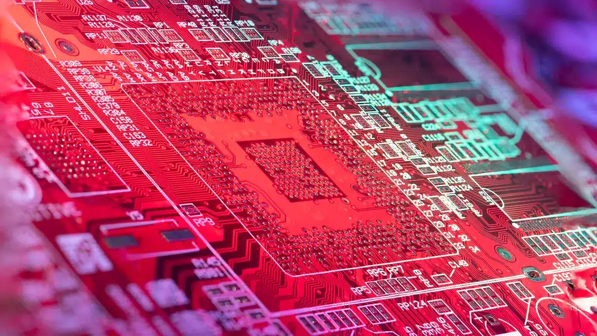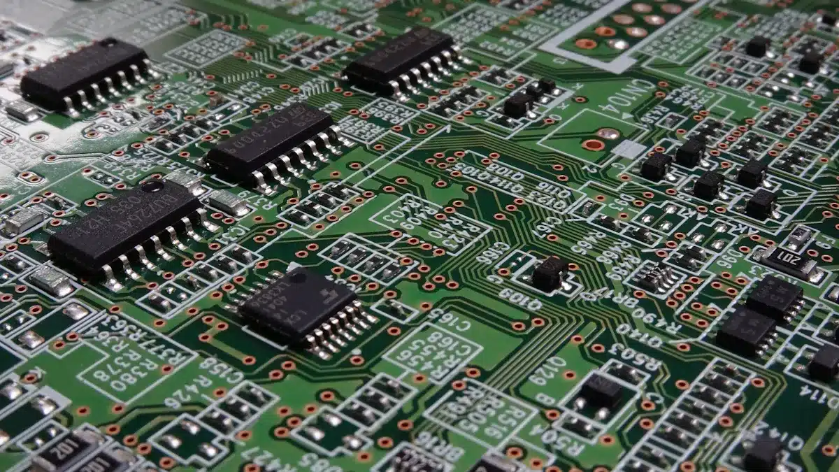
In electronics, picking the right pcb circuit board material is very important. It affects how well the board works and how reliable it is. The demand for printed circuit boards is growing. It is expected to reach $92.4 billion by 2029. So, knowing about different types of pcb materials is necessary. Industries like consumer electronics and automotive depend on the right circuit board. This helps them meet their needs. Choosing the right pcb material can greatly affect heat management, electrical performance, and overall function. This makes it important for engineers and designers to make smart choices.
Key Takeaways
Picking the right PCB material is very important. It helps with heat control, electrical performance, and how long devices last.
FR-4 is the most popular and affordable PCB material. It provides good strength and electrical insulation for many uses.
Metal core PCBs have aluminum or copper bases. They manage heat well, making them great for high-power devices like LED lights.
PTFE (Teflon) materials work well in high-frequency circuits. They reduce signal loss and resist heat and chemicals.
Engineers need to think about cost, strength, and heat needs. This helps them choose the best PCB material for each project.
Types of PCB Materials

When engineers choose pcb circuit board materials, they think about different types. These types depend on what they need and how well they perform. Knowing about the different PCB materials is important for good design and function.
FR-4 Material
FR-4 is the most common PCB material in use today. It is made of fiberglass and epoxy resin. This gives it great electrical insulation, strength, and heat resistance. It meets the UL94V-0 standard for being flame-resistant, which keeps electronics safe.
Key properties of FR-4 include:
Electrical Performance: FR-4 has good electrical insulation. This helps keep signals clear.
Thermal Stability: The glass transition temperature (Tg) is usually between 115°C and 200°C. This means it can handle soldering heat without changing shape.
Cost-Effectiveness: FR-4 is cheaper than many other materials. This makes it a favorite for making lots of printed circuit boards.
Because of these features, FR-4 works well in many areas, like consumer electronics, cars, and industrial devices.
Metal Core PCBs
Metal core PCBs (MCPCBs) use a metal base, usually aluminum or copper, to help manage heat. These materials are great for high-power uses where heat needs to be controlled.
The benefits of MCPCBs include:
Superior Thermal Conductivity: Aluminum can conduct heat between 138 and 237 W/m·K. Copper can go up to 401 W/m·K. This helps move heat away from parts, lowering the chance of overheating.
Simplified Design: MCPCBs do not need many thermal vias. The metal core helps with heat relief. This makes them easier to make and more reliable.
Durability: Metal bases make the PCB last longer. They are perfect for uses like LED lights and power converters.
MCPCBs are becoming more popular in fields that need good heat management, like cars and consumer electronics.
PTFE (Teflon) Material
PTFE, or Teflon, is a special material for high-frequency PCBs. Its unique features make it great for places where signal quality is very important.
Key features of PTFE include:
Low Dielectric Constant: PTFE has a dielectric constant of about 2.0 to 2.1. This reduces signal loss, making it perfect for RF and microwave uses.
Chemical Resistance: PTFE does not react with chemicals and repels water. This helps it keep its properties even in tough conditions.
Thermal Stability: This material works well at high temperatures. It is good for tough jobs in aerospace and telecommunications.
Industries that often use PTFE-based PCBs include aerospace, telecommunications, and medical devices, where reliability and performance matter a lot.
Properties of PCB Materials

The properties of PCB materials greatly affect how they work in different uses. Knowing these properties helps engineers pick the right materials for their needs. Two important properties are thermal management and electrical performance.
Thermal Management
Good thermal management is key to keeping electronic devices reliable and lasting longer. Different PCB materials have different thermal conductivity. This affects how well they can get rid of heat.
PCB Material | Typical Thermal Conductivity Range (W/mK) |
|---|---|
FR4 | 0.1 to 0.5 |
General Substrates | 0.3 to 0.6 |
Aluminum PCB | 1 to 9 |
Alumina Ceramic PCB | ~20 |
Aluminum Nitride PCB | ~180 |
Copper | ~386 |
The table above shows the thermal conductivity of common PCB materials. For example, copper has great thermal conductivity. This makes it perfect for high-power uses. On the other hand, FR4 is a common laminate but has lower thermal conductivity. This can limit its use in high-temperature situations.
Metal core PCBs, made from aluminum or copper, are great at getting rid of heat. They have a layer that absorbs heat and sends it to the metal base. This helps move heat away from sensitive parts. This feature makes them good for high-power circuits, like LED lights and power converters.
Tip: When designing PCBs for high-power uses, choose materials with high thermal conductivity. This helps with heat dissipation and stops overheating.
Electrical Performance
Electrical performance is another key property that affects how well a PCB works. Important factors include the dielectric constant, loss tangent, and moisture absorption.
Influence on Signal Integrity in High-Speed Circuits | |
|---|---|
Dielectric Constant (Dk) | Affects how fast signals travel and their impedance; low Dk materials reduce signal distortion and improve timing accuracy. |
Loss Tangent (Df) | Affects how much signal weakens over distance; low Df helps keep signal strength. |
Thermal Stability | Keeps electrical performance steady under temperature changes, stopping signal problems from heat. |
Moisture Absorption | Low moisture absorption keeps dielectric properties stable in humid places, helping signal integrity. |
Mechanical Strength | Keeps signal paths safe during making and use, preventing damage and errors. |
The dielectric constant of FR4 is about 4.5, which affects how fast signals travel. Materials with lower dielectric constants, like PTFE, help reduce crosstalk and improve signal quality in fast circuits. Also, the loss tangent shows how much signal is lost as it moves through the material. Low-loss materials are important for keeping signal strength over long distances.
Applications of Different PCB Materials
PCB materials are very important in many uses across different industries. Knowing how these materials are used helps engineers make smart choices when designing.
High-Frequency Applications
High-frequency applications need materials that keep signals clear and reduce losses. Good choices are ceramic-filled PTFE and hydrocarbon-based laminates. These materials have low dielectric constants and dissipation factors. This makes them great for RF and microwave circuits.
PCB Material Type | Dielectric Constant (Dk) Range | Dissipation Factor (Df) Range | Thermal Conductivity | Coefficient of Thermal Expansion (CTE) | Notes on Performance and Fabrication Challenges |
|---|---|---|---|---|---|
Ceramic-filled PTFE laminates | ~2.1 – 2.5 (design Dk) | ~0.002 | Moderate | Good (improved over pure PTFE) | Great electrical performance; hard to drill and prepare for plating |
Ceramic-filled hydrocarbon with woven glass | ~3.0 – 3.5 (design Dk) | ~0.003 | Moderate | Strong (CTE ≤ 70 ppm/°C) | Good mix of electrical performance and easy to make |
Micro fiber glass PTFE | ~2.1 – 2.4 | ~0.001 – 0.002 | Low | Poor dimensional stability | Best electrical performance; hard to make |
Standard FR-4 | ~4.2 – 4.5 | ~0.018 – 0.020 | Low | Higher CTE | Not good for high-frequency due to high losses |
These materials are key for uses like power amplifiers and high-power RF circuits. Engineers need to think about dielectric constant stability and low moisture absorption for reliable performance.
Flexible PCB Applications
Flexible printed circuit boards (FPCBs) are becoming popular because they are adaptable and light. They are often used in wearable tech, medical devices, and cars. The main material for flexible PCBs is polyimide, which is known for its great heat resistance and flexibility.
Key features of flexible PCBs include:
High Flexibility: They can bend and fold without breaking, which is good for small designs.
Durability: Flexible PCBs can handle tough conditions, ensuring they work well in moving applications.
Lightweight Design: Their light weight helps create portable devices.
In wearable tech, flexible PCBs help make fitness trackers and medical monitors that fit the user’s body. This flexibility improves comfort and device use.
Tip: When making flexible PCBs, use polyimide for its great mechanical properties and heat resistance.
These features let flexible PCBs support advanced functions in many uses, making them an important part of modern electronics.
Choosing the Right PCB Material
Picking the right pcb circuit board material needs careful thought about many things. Cost and strength are two important factors that engineers must check.
Cost Considerations
Cost is a big part of pcb material selection. Engineers should think about several cost factors when choosing materials for large projects:
Panel Fabrication Costs: This includes materials, labor, processing, and time needed. Each of these can change a lot based on the PCB materials picked.
Assembly Costs: Depending on how complex and how many parts there are, assembly costs can be as high as or higher than fabrication costs.
Component Costs: These costs matter too, but they are less affected by the PCB material choice.
Fixed Costs: Design and non-recurring engineering (NRE) costs are spread out over production volume, making them less important for material choices.
Economies of Scale: Making a lot of items can lower the cost per unit, so it’s important to design for larger runs.
Engineers also need to watch copper prices, as they can change and affect total costs. Common materials like FR4 are cheaper, while special materials for high-frequency uses can cost more.
Tip: When planning a project, think about both starting costs and long-term savings. Better materials may cost more at first but can save money on maintenance and improve reliability later.
Mechanical Strength Requirements
Mechanical strength is very important for keeping PCBs strong and reliable, especially in tough situations. Engineers must follow certain standards, especially in fields like aerospace. Key needs include:
Following military and industry standards like MIL-PRF-31032 and IPC-6012.
Vibration testing according to MIL-STD-810 to check resistance to stress.
Using strong mounting holes and adhesives to hold parts against vibrations.
Doing finite element analysis (FEA) during design to find weak points and improve strength.
Materials like polyimide and ceramic substrates are very strong, making them great for uses that face a lot of stress and temperature changes.
Note: Choosing the right substrates is key for keeping performance under stress. Engineers should think about the working environment and possible loads when picking materials.
By balancing cost and strength, engineers can make smart choices that improve the performance and life of their printed circuit boards.
Choosing the right PCB material is very important for getting the best performance in electronic designs. Engineers need to think about different things when they make their choices, such as:
FR-4: This is cheap and has good strength and electrical features. It works well for many uses.
Polyimide: This material can handle high heat, making it great for hot places.
Ceramic-Based PCBs: These have great heat flow and electrical insulation. They are good for high-power uses.
Rogers Laminates: These are best for RF and microwave circuits because they lose less signal.
Metal Core PCBs: These help manage heat better, making them great for LED lights and power converters.
By knowing what each application needs and how materials work, engineers can make sure their designs last a long time and perform well. This careful planning helps reduce maintenance and improves how long the product lasts.
FAQ
What is the most common PCB material used in electronics?
FR-4 is the most common PCB material. It is made of fiberglass and epoxy resin. This gives it great electrical insulation, strength, and heat resistance. It is also affordable, making it a popular choice for many uses.
How do metal core PCBs manage heat?
Metal core PCBs have a metal base, usually aluminum or copper. This helps them get rid of heat well. This design improves heat flow, making them perfect for high-power uses like LED lights and power converters.
What are the advantages of using PTFE in PCBs?
PTFE, or Teflon, has a low dielectric constant and great heat resistance. These features make it good for high-frequency uses, like RF and microwave circuits, where keeping signals clear is very important.
How does the choice of PCB material affect performance?
The PCB material chosen affects heat management, electrical performance, and strength. Engineers need to think about these things to make sure their designs are reliable and work well.
What factors should engineers consider when selecting PCB materials?
Engineers should look at cost, heat flow, electrical performance, and strength. Knowing the specific needs of the application helps in picking the best material for the best performance.
See Also
Understanding How PCBA And PCB Differ In Function And Design
Unveiling The Key Distinctions Between PCBA And PCB Technology
Comparing PCBWay With Other PCB Manufacturers In Depth