When you start a new project, choosing the right pcb board matters. You need to think about what is a pcb board and how it fits your project needs. Many engineers look at these important factors:
Number of layers and material type
Thickness and copper weight
Signal and power integrity
Compliance with safety standards
Heat resistance and thermal conductivity
Design rules for trace width and spacing
You will find clear explanations for each term. Simple steps help you avoid mistakes and make smart choices for your pcb.
Key Takeaways
First, decide what your project needs. Think about size, function, and where it will be used. This helps you pick the right PCB type and materials.
Choose PCB materials and thickness that fit your project’s needs. Make sure they can handle heat, moisture, and last a long time.
Make your PCB design with the right trace widths and spacing. Use good layouts to keep signals strong and safe.
Work with your manufacturer and share clear drawings and files. Give them a detailed bill of materials to stop mistakes and delays.
Follow industry rules and do not make common mistakes. Good thermal management and clear paperwork help you build a strong PCB.
What Is a PCB Board
PCB Board Basics
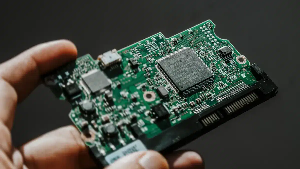
When you ask about a pcb board, you start with simple ideas. A pcb, or printed circuit board, links electronic parts with copper lines. These boards are inside almost every electronic device. You see them in things like calculators and smartphones. The pcb holds parts such as resistors, capacitors, and chips. It acts like the backbone for your project. It gives support and helps signals move to the right places.
You may wonder how a pcb works in different circuits. In analog circuits, the board must block noise and keep signals clear. In digital circuits, the board deals with fast switching and high currents. The table below shows some main differences:
Aspect | Analog PCB Functions | Digital PCB Functions |
|---|---|---|
Noise Sensitivity | Must block noise and stop interference. | Handles more noise and manages fast switching. |
Component Placement | Puts parts close together to lower interference. | Uses special layouts to control switching noise. |
Ground Plane Design | Keeps ground paths clear and away from digital noise. | Uses big ground planes for high currents. |
Types of PCB Boards
You need to know about pcb board types before picking one. Each type has its own structure and use. The table below helps you compare single-layer, double-layer, and multi-layer boards:
PCB Type | Structure Details | Characteristics and Complexity | Applications and Usage Examples |
|---|---|---|---|
Single-layer | Has one copper layer on a base. Parts go on one side. | Simple, cheap, easy to fix. | Used in calculators, LED lights, printers. |
Double-layer | Has two copper layers with links between them. Parts can go on both sides. | More complex, higher circuit density, stronger. | Used in mobile phones, power supplies, controls. |
Multi-layer | Has three or more copper layers stacked up. Vias connect the layers. | Very complex, tough, hard to repair. | Used in aerospace, medical devices, advanced electronics. |
You also see flexible pcb boards in wearables. These boards bend and twist to fit tight spaces. Flexible boards save space and weight. They cost more and need careful design.
When you ask about a pcb board, you learn it is more than a flat piece. It is a key part of every electronic project. You must pick the right type and design for your needs.
Project Requirements
Before you pick your pcb, you need to know your project needs. This step helps you avoid mistakes and makes sure your pcb works for your project. Think about how your pcb will work, where it will go, and what it will face. Write down these needs so you can talk with your pcb maker and get the right board.
Functional Needs
Your project starts with a clear goal. You must decide what your pcb will do. Will it control lights, check temperature, or connect to a computer? Write down every job your pcb must do. This helps you pick the right parts and layout.
You should give these details to your pcb maker:
Netlist files that list all electrical links.
Fiducials for lining up during making.
Steps for putting and soldering parts.
Test steps and tools to check your pcb.
In-circuit test needs for quality checks.
X-ray checks for solder joints.
Rules and standards, like RoHS or IPC.
A golden sample to show good quality.
A list of work that shows your project and goals.
Tip: Always check your files before you send them to your pcb maker. Clear files and notes help stop mistakes and delays.
You also need to add drawings, design files, and assembly files. These show your pcb thickness, layer count, and part spots. A bill of materials (BOM) lists every part and its details. Good layout and same part direction help stop mistakes and make your pcb work better.
Size and Shape
The size and shape of your pcb change how it fits in your project box. You must measure the space inside your product and pick a pcb shape that fits. Rectangle boards fit normal boxes, but special shapes work for unique designs.
PCB size and shape decide if your board fits your project box.
Small pcbs work best in wearables and tiny devices, but need careful layout.
Plated holes help with grounding and lower noise.
Non-plated holes are for holding the board.
Common Shapes | Application Examples | Impact on Project | |
|---|---|---|---|
Rectangular | Standard enclosures | Computers, routers | Easy to design and mount |
Circular | Wearables, sensors | Smartwatches, sensors | Fits round housings |
Irregular | Custom housings | Drones, medical devices | Matches unique spaces |
Plan your mounting holes. Put them in corners for balance and keep them away from busy areas. This stops stress and noise. The right pcb thickness matters too. Thick boards are strong but cost more. Thin boards save space but may bend or break.
Note: Picking the right shape and pcb thickness early helps you avoid changes and makes sure your pcb fits your project.
Environmental Factors
Your project may face heat, water, shaking, or chemicals. You must pick pcb materials and pcb thickness that match these things. The table below shows how each factor changes your choice:
Impact on PCB Selection | Suitable Materials and Properties | |
|---|---|---|
Temperature | Needs high heat resistance for good life and parts | FR-4 (up to 130°C), Polyimide (up to 260°C), Ceramic for heat spreading |
Humidity and Moisture | Water can cause swelling, shorts, and problems; needs water-proof | PTFE (water proof), Acrylic or silicone coats for safety |
Mechanical Durability | Needs to handle shaking, hits, and movement to stop cracks | Flexible stuff like Polyimide, PEN for bending and stress |
Radiation Resistance | Needs to block radiation to stop damage | PTFE and Polyimide are good for blocking radiation |
Thermal and Electrical Conductivity | Needs good heat spreading and electric work | Ceramic (like aluminum nitride) for heat; thick copper for electric work |
Electrical Properties | Needs low loss and good signal | Rogers stuff for low loss and good signals |
Standards Compliance | Must meet rules for rust, heat, and strength | Special FR-4 types like FR-408HR |
Pick pcb thickness that matches your project place. Hot places need boards that handle heat well. Wet places need water-proof stuff and coats. If your project shakes, pick flexible stuff and strong mounting. Chemical safety is key for factories.
Tip: Always tell your pcb maker about your project place. This helps them pick the right stuff and pcb thickness for your board.
Write down your needs with big drawings and notes. Add stackup views, drill charts, and steps for building. List every special need, like controlled impedance or solder mask color. A full BOM and schematic help your pcb maker build your board without mistakes.
Component & Material Selection
Component Compatibility
You must make sure your parts and board materials work together. If you mix parts with different properties, problems can happen. For example, if the board and parts expand at different rates, the layers can peel off. This makes the board weak and can break signal paths. If water gets trapped in the board, it can build up pressure when heated. This can cause the layers to come apart and damage the board. Using materials that handle heat and water the same way helps stop these problems. Adding moisture barriers and strong glue gives extra safety. Always match your parts and materials when you choose them. This keeps your pcb safe and helps your project work well.
Material Options
You can pick from many pcb materials. FR-4 is the most used. It works well for most electronics. FR-4 is cheap, easy to shape, and resists fire. It works for signals up to 1 GHz. But it does not handle heat or high-frequency signals as well as some other materials.
Property | FR-4 PCB | Aluminum PCB |
|---|---|---|
Thermal Conductivity | Low (~0.3 W/m·K) | High (1-2 W/m·K) |
Cost | Economical (~$0.10 per sq inch) | More expensive ($0.15-$0.30 per sq inch) |
Frequency Suitability | Suitable up to ~1 GHz | Not ideal for high-frequency use |
Applications | Phones, tablets | LED lighting, power supplies |
If your project gets very hot, you may need polyimide or metal core boards. These can handle more heat and have higher glass transition temperatures. You should also think about pcb thickness. Thick boards can take more heat and stress but cost more. Thin boards save space but can bend or break.
Cost and Availability
The material you pick changes the price and how fast you get your pcb. FR-4 is cheap and easy to buy, so it is good for big orders. Special materials like polyimide or PTFE cost more and may take longer to get. Using thicker copper or more layers also makes the price go up. You need to find a balance between cost and how well your board works.
If you want to make many boards, your budget matters. Using common materials and simple designs saves money and time. Complex boards with special materials or extra pcb thickness cost more. You should talk to your manufacturer to get the best deal for your needs.
Tip: Always check if your materials and parts are easy to get before you finish your choice. This helps you avoid waiting and keeps your project moving.
Electrical & Mechanical Specs
Current and Signal
When you design a pcb, you need to think about how much current your traces can handle. You also need to make sure signals move well across the board. Both current and signal quality affect how your project works.
If you use wide and thick traces, your pcb can carry more current. Thin traces can get too hot and break.
Short traces help keep signals strong. Long traces can make signals weak and cause heat.
The width, thickness, and length of each trace all matter. For example, a trace that carries 5A and gets 10°C hotter may need to be 0.75mm wide on a 1oz copper layer.
Use pcb trace width calculators to pick the right size. This helps stop overheating and keeps your board safe.
Put vias close together and use through-hole vias for high-current paths. This helps with heat and makes the board work better.
Keep enough space between traces. This stops shorts and keeps signals clear.
Signal quality is just as important as current. You want signals to move without getting messed up or lost. Here are some ways to help signals:
Use controlled impedance by picking the right trace width, thickness, and spacing. This keeps impedance steady, often at 50 ohms, and stops signal reflections.
Route differential pairs together for fast signals like USB 3.0. This lowers noise and keeps impedance steady.
Pick pcb materials with stable dielectric constants, like FR-4, to keep impedance the same.
Add termination resistors near the source to match impedance and stop signal reflections.
Choose materials with low dielectric constant (Dk) and low loss tangent (Df). This helps stop signal loss, which is important for fast designs.
Tip: For telecom equipment, use multilayer stack-ups with special ground and power planes. This controls impedance and lowers electromagnetic interference, which helps your board work better.
Durability
You want your pcb to last, especially if it faces tough places. Durability depends on the materials you pick and how you design your board.
Outdoor pcbs face heat, water, and chemicals. These can cause rust, shorts, or even break the board.
Vibration, drops, and hits can hurt your pcb. Thin boards can bend or crack when stressed.
Electrical problems like shorts and static can also hurt your board.
You can protect your pcb with conformal coatings. Acrylic, polyurethane, silicone, and UV-curing coatings keep out water, dust, and chemicals.
Good hole placement is important. If holes are too close to copper, you can hurt signal paths and make the board weak.
Make sure annular rings (the copper ring around holes) are big enough. Small rings can break and make solder joints weak.
Note: Always design for where your pcb will be used. If it will be outside, plan for temperature changes, water, and bumps.
Factors to Consider in PCB Thickness Selection
Picking the right pcb thickness is very important. The thickness of your board changes how strong it is and how well it works.
Thick pcbs are stronger. They do not bend, warp, or break easily. This is good for cars, factories, and planes.
Thick boards also spread heat better. This helps stop hot spots and makes high-power devices work better.
If you use thick copper layers, you can carry more current and spread heat better.
Thin pcbs are light and bendy. They are good for wearables and small devices but may not handle heat or stress well.
If your board is too thin, it can bend or break during use or when being made. This can hurt how strong it is and how well it works.
Here is a table that shows common pcb thickness choices and where you might use them:
PCB Thickness | Typical Use Cases | Benefits | Drawbacks |
|---|---|---|---|
0.2mm–1.0mm | Wearables, compact electronics | Lightweight, flexible | Less durable, poor heat spread |
1.2mm–1.6mm | Consumer electronics, computers | Balanced strength and flexibility | Standard for most projects |
2.0mm–3.2mm | Automotive, aerospace, industry | High strength, good heat spread | Heavier, higher cost |
For cars and planes, use pcb thickness between 2.0mm and 3.2mm. These thick boards can handle lots of current, spread heat well, and do not break from shaking or pressure. In these areas, you need your board to be strong and work well.
Tip: Always balance strength, heat control, weight, and flexibility when you pick pcb thickness. The right choice makes your board last longer and work better.
Manufacturing & Assembly
Manufacturability
When you pick a pcb, think about how easy it is to make. Your design should match what your pcb manufacturer can do. You want your board simple to build and put together. First, the manufacturer chooses the right base and copper thickness. Then, lasers or UV light make the circuit patterns on the board. Chemicals take away extra copper so the circuits are correct. Machines drill holes for the parts, which helps the board fit well. Plating and finishes like HASL or ENIG keep copper safe and help with soldering. Layers are pressed together for strong multilayer boards. Checks like looking and X-rays find problems early. The manufacturer puts parts on the board using SMT or through-hole assembly. Soldering, like wave or reflow, holds the parts in place. At the end, tests make sure every connection works. All these steps help you get a pcb that works well and lasts long.
Quality and Reliability
You want your pcb to work well for a long time. Quality checks are important at every step. Makers look at the board, use machines, and take X-rays to find problems. In-circuit tests check for open or short circuits and test the parts. Functional tests act like real use to see if the pcb works right. Stress tests put the board in heat, wet, and shaking to check strength. Special methods like Six Sigma help lower mistakes and make things better. Pick a pcb maker with good skills and strong testing rules. Standard tests like IPC-TM-650, IPC-6012, and MIL-STD-202 make sure your board meets the rules. The table below shows how these standards help with quality and reliability:
Standard Name | Role in PCB Reliability Testing | Typical Test Items | Key Reliability Aspects |
|---|---|---|---|
IPC-TM-650 | Test methods for reliability evaluation | Thermal cycling, peel strength | Thermal/electrical stress, insulation failure |
IPC-6012 / IPC-A-600 | Acceptance criteria and inspection | Delamination, hole integrity | Manufacturing consistency, material integrity |
MIL-STD-202 / MIL-STD-883 | Military/aerospace reliability | Vibration, mechanical shock | Extreme environment adaptation, long-term stability |
JEDEC | System-level reliability verification | Moisture sensitivity, solder reliability | Moisture-induced failure, solder fatigue |
ISO 9001 / IATF 16949 / ISO 13485 | Quality management systems | Process capability, traceability | Full-process reliability management, quality assurance |
Production Volume
How many pcbs you need changes how you make them. For small numbers or testing, people can put parts on by hand. This costs less at first and lets you change things. For lots of boards, machines put parts on fast and the same way every time. This saves time and makes better boards. You should match how you make boards to how many you need. Good panel design helps save materials and money. Your pcb maker will plan panels to fit your product and SMT line. Different ways to make panels change how hard and good the boards are. For small amounts, quick methods like milling or 3D printing save time and money. For big orders, machines do etching and assembly for better quality and speed. Talk to your maker to match your skills and needs. This helps you balance cost, quality, and how well your board works.
Compliance & Standards
Industry Standards
When you make a PCB board, you must follow certain rules. These rules are called industry standards. They help you make sure your board is safe and works well. Many groups create these rules for PCB boards. Some important groups are IPC, ISO, UL, and military groups. These rules tell you how to check, test, and build your board. If you follow them, your board will last longer and work better.
Here is a table that lists some main standards and what they do:
Standard/Certification | Description | Application/Scope |
|---|---|---|
Gives rules for putting boards together and checking quality | Used by electronics companies to make good PCBs | |
ISO (e.g., ISO 9001:2015, ISO 13485) | Focuses on making sure quality stays high | Used for medical devices and other products |
UL (e.g., UL 796) | Checks for safety, fire, and shock problems | Makes sure PCBs are safe to use |
Controls products for the military | Needed for making military PCBs | |
Sets quality rules for airplanes and space | Used by companies making aerospace PCBs | |
Limits dangerous stuff in boards | Makes boards safer for the environment | |
MIL Standards | Has strict rules for military PCBs | Used for defense and military projects |
You should always find out which rules fit your project. Following these rules helps you make better boards and avoid trouble later.
Safety Certifications
Safety certifications help keep people safe and make sure your PCB board meets tough rules. If you make boards for medical devices, you need to do extra steps for top quality. Some important safety certifications are:
ISO 13485: This is needed for medical device makers. It checks if you control risks and design well.
FDA 21 CFR Part 820: You must follow these rules for medical devices in the U.S. They cover design, testing, and keeping records.
IEC 60601: This checks safety for medical electrical equipment. It looks at risks like shock and signal problems.
UL 94: This rating tests how well PCB materials stop fire. It helps you pick safe materials.
IPC-6012 Class 3: This rule sets the highest quality for medical and military PCBs. It checks every detail to make sure your board works in hard places.
ISO 10993: This test checks if materials are safe for the body. You need this for boards that touch or go inside the body.
Cleanroom Manufacturing: Some medical boards need clean rooms. This keeps dust and germs away and helps you reach top quality.
You should always try to get the right safety certifications. These steps help you make strong boards and keep users safe.
Common Mistakes
You can stop many problems if you learn from common mistakes. Many engineers make these errors. This can slow down your project or cost more money. Sometimes, it can even make your project fail.
Frequent mistakes during PCB selection include:
Poor thermal management. If your board cannot lose heat, it may get too hot and break.
Signal integrity issues. Bad layouts can mess up signals and make them weak.
Lack of testability. Without test points, it is hard to check or fix your board.
BOM discrepancies. If your bill of materials does not match your parts, you may have trouble putting the board together.
Inadequate clearances and spacing. Not enough space between traces can cause shorts or make assembly hard.
Errors in design files and documentation. Missing or old files can slow your project and confuse your manufacturer.
Tip: Always check your design files and BOM before you send them. Clear and updated documents help stop expensive mistakes.
You should also look out for these technical errors:
Improper trace width and spacing. Traces that are too thin can get hot and break.
Overlooking via sizes. Wrong via choices can hurt signals and cause problems when making the board.
Ignoring power and ground plane layouts. Bad designs here can make noise and give unstable power.
Neglecting design for manufacturability. If your design does not match what your manufacturer can do, you may have delays and pay more.
Improper decoupling capacitor placement. If capacitors are too far from IC pins, they will not work well.
For high-frequency projects, you need to be extra careful. Use materials with low dielectric loss, like Rogers or Isola, instead of FR-4. Keep enough space between high-speed traces—at least three times the trace width—to lower crosstalk. Always use simulation tools to check your design before making the board. This helps you find problems early and keeps your signals strong.
Remember, planning and paying attention to details help you avoid these common mistakes and build a good PCB for your project.
Picking the right PCB board is easier if you follow these steps:
Figure out what your project needs and what stage you are at.
Choose materials that are strong for electricity, heat, and movement.
Decide how many boards you need to make for your project.
Make a list of manufacturers who have good help and the right certificates.
Check the prices, how long it takes to get your boards, and how they check for quality.
Stay in touch with your manufacturer from the beginning.
It is smart to talk to PCB experts early. They can help you fix design problems, choose the right materials, and follow the rules for your project. If you want to ask something or share your story, write a comment below! 👇
FAQ
What is the most important factor when choosing a PCB board?
You should always start with your project’s needs. Think about what your board must do, where it will go, and how much power it will handle. This helps you pick the right type and material.
How do I know which PCB material to use?
You can match the material to your project’s environment. For hot places, use polyimide or ceramic. For most electronics, FR-4 works well. Ask your manufacturer if you feel unsure.
Can I use a thin PCB for any project?
No. Thin PCBs work best in small, light devices. If your project faces heat, vibration, or heavy use, you need a thicker board for strength and safety.
What documents should I give my PCB manufacturer?
Drawings with size and shape
Bill of materials (BOM)
Design files
Assembly instructions
Clear documents help your manufacturer build your board without mistakes.
See Also
Best Advice For Selecting The Ideal Main PCBA
Crucial Guidelines To Pick The Perfect PCBA Board
Important Factors To Evaluate When Selecting PCB Or PCBA