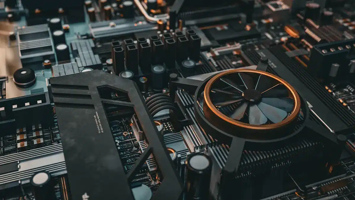
A circuit card assembly is a finished unit. It holds and connects electronic parts on a circuit card. This assembly is like the backbone of modern devices. It lets each part send signals and power across the circuit card. The circuit card assembly helps parts talk to each other and work together. It makes sure devices do their jobs the right way. Without circuit card assemblies, electronic devices would not work. Their parts could not connect or interact.
Key Takeaways
A circuit card assembly (CCA) is a circuit board with all its electronic parts attached. This helps devices work the right way.
CCAs use many materials and parts like resistors, capacitors, and integrated circuits. These parts help control electricity and signals.
The manufacturing process has steps like placing parts, soldering, and testing. These steps make sure the assembly works well and is reliable.
CCAs are not the same as bare printed circuit boards (PCBs). CCAs have all their parts installed and are ready to use in devices.
Circuit card assemblies are very important in many industries like computers, cars, healthcare, and aerospace. They help devices work safely and well.
Circuit Card Assembly Basics
What Is a Circuit Card
A circuit card is the base for most electronics. In electronics, a circuit card is also called a printed circuit board. This name shows it is a flat, hard surface that holds and connects parts. People often use “card” and “board” to mean the same thing. Some fields, like aerospace, use “circuit card” to avoid mix-ups with other materials.
A circuit card gives a place to put and connect parts. It has copper lines that act like roads for electricity. These lines join parts so they can work together. How a circuit card is made decides how well the device works.
Note: “Circuit card assembly” means the card with all its parts attached. This finished unit lets the device do its job.
Makers use different stuff to build circuit cards. The table below lists common materials and what they are used for:
Material Type | Composition / Description | Typical Use / Notes |
|---|---|---|
FR-2 | Phenolic cotton paper with phenol formaldehyde resin | Used in consumer electronics, single-sided boards, lower cost, lower performance |
FR-4 | Woven fiberglass cloth with epoxy resin | Most common, good insulation, used in many printed circuit boards |
Aluminum-based boards | Metal core with aluminum and copper layers | Used for heat dissipation in power devices and LEDs |
Flexible substrates | Copper-clad polyimide foils | Used in flexible circuits, small devices, high temperature resistance |
CEM series (CEM-1 to 5) | Cotton paper or glass fiber with epoxy or polyester resin | Alternative laminates with different properties |
PTFE (Teflon) | Polytetrafluoroethylene, sometimes ceramic-filled | High frequency applications, low dielectric loss, expensive |
Alumina | Ceramic material | High performance, very expensive, excellent thermal conductivity |
Polyimide | High-temperature polymer | Used for high-performance, high-temperature applications |
A circuit card can be stiff or bendy, based on what the device needs. Most home electronics use stiff circuit boards. Bendy circuit cards are used when things need to fit in small or odd spaces.
Key Components
A circuit card assembly only works when it has the right parts. These parts help the device handle signals, power, and connect to other things. The main parts of a circuit card assembly are both active and passive. The table below shows the main parts and what they do:
Component Type | Function and Description |
|---|---|
Resistors | Limit electrical current, control current levels, and divide voltage |
Capacitors | Store and release electrical energy, filter signals, stabilize voltage, and manage power fluctuations |
Inductors | Store energy as magnetic fields, resist changes in current, used in filtering and tuning |
Transistors | Act as switches or amplifiers, control current flow |
Diodes | Allow current flow in one direction, used for rectification and signal demodulation |
Integrated Circuits (ICs) | Miniaturized circuits combining multiple components, used in analog and digital applications |
Board-to-Board Connectors | Connect multiple printed circuit boards for communication between modules |
I/O Connectors | Interface the circuit card assembly with external devices for data or power transfer |
Wire-to-Board Connectors | Connect wires from sensors or actuators to the pcb, designed for flexibility without signal loss |
High-Frequency Connectors | Connect radio frequency and microwave signals with minimal loss through shielding |
FPC/FFC Connectors | Connect flexible printed circuits and flat flexible cables for flexible electronics |
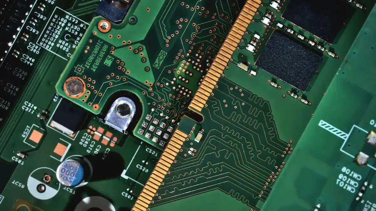
The printed circuit board is the base of the assembly. It has several layers:
Substrate: The main layer, usually fiberglass or polyimide.
Copper Traces: Thin lines that move electricity between parts.
Solder Mask: A cover that stops rust and mistakes.
Silkscreen: Labels that help people find parts during building.
The main parts of a circuit card assembly work together to run the device. Each part has its own job:
Resistors set how much current and voltage can go through. They keep parts safe and help set things like sound or light.
Capacitors hold and let go of energy. They clean up signals, keep voltage steady, and help with timing.
Integrated circuits put many jobs into one chip. They do things like handle signals, control power, and run logic.
Other parts, like diodes, transistors, and inductors, add more control and features. Connectors let the assembly link to other boards or devices. These links help the device send and get data or power.
A good circuit card assembly uses the best mix of parts. Picking the right ones helps the device work well and last longer. Teams who build circuit boards must know how each part fits in the design.
Tip: Picking the best materials and parts for a circuit card can make devices work better and last longer.
Circuit Card Assembly Manufacturing Process
Circuit Card Assembly Steps
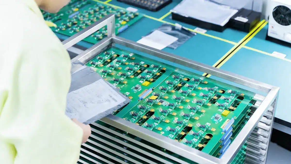
The circuit card assembly process changes a plain pcb into a working unit. Each step adds something new to the circuit card. The main steps are:
Solder Paste Application: Technicians put solder paste on the pcb pads with a stencil. The paste keeps parts in place before they are soldered.
Component Placement: Machines put resistors, capacitors, and other parts on the circuit card. They do this with great accuracy.
Reflow Soldering: The pcb goes through a hot oven. The heat melts the solder paste and makes strong connections.
Through-Hole Component Insertion: Workers or machines put parts with leads into holes on the circuit card.
Wave Soldering: The board moves over melted solder. This step locks through-hole parts in place.
Inspection and Testing: Quality checks make sure all parts are in the right spot and work well.
These steps link all the parts to the copper lines on the circuit card. The process turns a simple board into a full circuit card assembly that powers devices.
Soldering Methods
Soldering connects parts to the circuit card. The main ways to solder are:
Soldering Method | Typical Use Case | Process Description | Key Differences |
|---|---|---|---|
Wave Soldering | Through-hole components | The pcb goes over melted solder to join leads in holes. | Best for many through-hole parts. |
Reflow Soldering | Surface mount components | Solder paste melts in an oven and sticks parts to pads. | Great for small, surface-mounted parts. |
Selective Soldering | Heat-sensitive or special areas | Solder goes only where needed to protect delicate parts. | Used when heat could hurt some parts. |
Intrusive Soldering | Through-hole components | Solder paste fills holes, then melts in the oven to make joints. | Mixes paste and reflow for through-hole parts. |
Each way works for different parts and circuit card designs. The best method depends on what the circuit card assembly needs.
Inspection and Testing
Inspection and testing help keep the circuit card assembly safe and reliable. Teams use these ways:
Manual Inspection: Workers look at the circuit card to find problems, missing parts, or bad solder.
Automated Optical Inspection (AOI): Machines scan the pcb for mistakes like misplaced parts or solder issues.
X-ray Inspection: This finds hidden problems under big chips or inside solder joints.
In-Circuit Testing (ICT): Probes check the electrical paths for shorts or open spots.
Functional Testing: The finished circuit card assembly is tested in real situations to make sure it works.
Industry rules like IPC and ISO guide these tests. These steps make sure each circuit board assembly is safe and high quality before use.
Circuit Card Assembly vs PCB and PCBA
Definitions
A printed circuit board, or pcb, is a flat board made from a material that does not let electricity pass through. It has copper lines that act like roads for electricity. The pcb is the base for electronic circuits, but it cannot work alone. A circuit card assembly, or CCA, is a pcb with all the needed electronic parts attached. These parts are things like resistors, capacitors, integrated circuits, and connectors. When all the parts are put on and soldered, the assembly can work as an electronic unit. A printed circuit board assembly, or PCBA, is another name for a finished pcb with all its parts installed and soldered. The PCBA is ready to be used in electronic devices.
A PCBA is the finished board after all electronic parts have been soldered and put on a pcb. It is a working electronic circuit.
Differences
The biggest difference between a pcb, a circuit card assembly, and a PCBA is what they do and when they are made. A pcb is just the base. It does not have any electronic parts. A circuit card assembly and a PCBA both have all the parts attached, so they are ready to use. The words CCA and PCBA usually mean the same thing, but some jobs use one word more than the other.
The table below shows the main differences:
Aspect | PCB (Printed Circuit Board) | Circuit Card Assembly (CCA) | PCBA (Printed Circuit Board Assembly) |
|---|---|---|---|
Definition | Bare board with copper lines | PCB with all parts attached | |
Components | None | Has resistors, capacitors, ICs | Has resistors, capacitors, ICs |
Functionality | Does not work by itself | Works as an electronic circuit | |
First step | Last step | Last step | |
Usage | Base for circuits | Ready to go into a device | Ready to go into a device |
The difference between circuit card assembly and pcb assembly is mostly just the name. Both mean a pcb with all its parts put on and soldered. The choice between circuit card assembly and pcb assembly can depend on the job or company, but both mean a finished, working circuit that is ready to use.
Circuit Card Assembly Applications
Common Uses
Circuit card assemblies are important in many things we use. You can find them in computers, home gadgets, and entertainment systems. Here are some ways circuit card assemblies are used:
Personal computers need circuit card assemblies to connect parts. Laptops, desktops, and their accessories all use them.
Home appliances like coffee makers and fridges use these assemblies. They help control power and signals in these devices.
Entertainment systems, like gaming consoles and stereos, use circuit card assemblies. They help send sound and video.
These devices need good circuit card assemblies to work well. As more things connect to the internet, strong assemblies are needed even more. There are single-sided, double-sided, and multilayer boards. Each type helps with different jobs and device needs.
Note: Picking the right circuit card assembly helps devices last longer and work better.
Industry Examples
Many industries use circuit card assemblies to make things work better. Each industry has special needs and uses different types of assemblies.
Industry | Example Applications |
|---|---|
Automotive | Engine controls, dashboard switches, digital screens, anti-lock brakes, navigation, LED lighting |
Aerospace | Navigation, radar, communication, power supplies, sensors, control systems |
Healthcare | MRI scanners, blood sugar monitors, pacemaker analyzers, electrocardiographs |
Industrial | Robotics, factory automation, power converters, temperature sensors |
UAVs, weapon systems, surveillance, electronic warfare, cybersecurity hardware | |
Communications | Networking equipment, radio, satellite communications, encryption devices |
Cars can have up to 45 circuit boards inside. These boards must work in heat, shaking, and wet places. Aerospace and defense need assemblies that work in tough conditions. Medical devices need safe and strong assemblies. These fields use rigid, flexible, and rigid-flex boards. Each kind helps meet the needs of the job.
Tip: Using the best assembly type and checking quality helps devices work their best.
Circuit Card Assembly Manufacturing Challenges
Production Issues
Manufacturers have many problems when making circuit card assemblies. These problems can hurt quality and reliability. Some common problems are:
Layers can be put in the wrong place. This can cause signal trouble or short circuits.
Solder mask might not go on evenly. This can cause defects, rust, or solder to touch where it should not.
Sometimes, electrical tests miss broken boards. Bad boards can pass inspection.
Mistakes in assembly can happen. Parts might be put in the wrong spot or soldered badly. This can make devices stop working.
Design mistakes can cause problems with heat. Bad part placement or wrong trace paths can make things too hot.
Picking the wrong materials can make the board weak. It can also hurt how well it works with electricity.
Problems like layers coming apart or bad copper can make the board break easier.
Dust, water, or big temperature changes can hurt the board. These things can cause rust or break solder joints.
Measling shows up as white spots. It means something inside the board got damaged during making.
Trouble getting parts can slow down making boards. It can also make things cost more.
When parts are hard to get, it slows down production. Prices go up and companies may need to use different parts. This can make products work worse or break easier. To fix this, companies use more than one supplier. They also buy from local or online stores to keep making boards.
Recent Advances
New technology has made circuit card assembly better. Surface-mount technology lets makers use smaller parts. This makes devices smaller and stronger. Flexible PCBs can bend and twist. This helps make new shapes and designs.
Robots and machines help build circuit card assemblies now. Pick-and-place robots and inspection machines work fast and make fewer mistakes. These machines help products work better. For example, robots can make things 30% faster and give 20% more good boards. Robots also help when companies make many different products in small amounts.
Better design software and computer tools help engineers. They can make boards that are more complex and work better. High-Density Interconnect and laser imaging let boards be even smaller and stronger. Greener ways of making boards help save energy and cut down on waste.
Circuit card assemblies make simple boards smart so devices can think. They use new ways like surface mount technology and machines that check for mistakes. This helps things like phones and medical tools work well and last longer.
CCAs link and power parts so devices are safe and work right.
Good assembly stops problems and helps new ideas in many fields.
Knowing how CCAs are made helps people see the skill and tech in electronics.
Term | What It Means |
|---|---|
PCB | The plain board with copper lines |
CCA | The board with all parts on and working |
PCBA | Another name for a finished, working assembly |
When you notice CCAs, you see the hidden hard work that makes modern life possible.
FAQ
What is the main purpose of a circuit card assembly?
A circuit card assembly connects and supports electronic parts. It lets electricity flow between components. This assembly helps devices work by linking all the parts together.
How does a CCA differ from a PCB?
A PCB is just the board with copper lines. A CCA has the board plus all the electronic parts attached. The CCA can work in a device, while the PCB cannot.
Why do some industries use the term “circuit card assembly” instead of “PCBA”?
Some industries, like aerospace and defense, use “circuit card assembly” to avoid confusion. This term helps them stay clear about which part of the device they mean.
What happens if a circuit card assembly fails?
If a circuit card assembly fails, the device may stop working or act strangely. Technicians often test and replace the faulty assembly to fix the problem.
Can a circuit card assembly be repaired?
Yes, technicians can repair some circuit card assemblies. They may replace broken parts or fix bad solder joints. Not all assemblies can be fixed, especially if damage is severe.
See Also
Understanding The Process And Main Stages Of PCBA Assembly
The Importance And Basics Of In-Circuit Testing In PCBA
Exploring Functional Circuit Testing And Its Role In PCBA