
PCBA design means planning how a circuit board looks and works. It connects and powers parts like resistors, capacitors, and microchips. This helps all the parts work well together. Without PCBA design, gadgets like phones, smartwatches, and medical tools wouldn’t work.
Did you know? About 70-80% of product costs are decided during design. PCBA design helps control these costs and makes devices smaller and better. From hospitals to space travel, PCBA design is key to building future technology.
Key Takeaways
PCB design is important for linking and powering electronic parts. It helps devices like phones and medical tools work correctly.
A good PCB plan can lower production costs and make devices more reliable by catching mistakes early.
Knowing the layers and parts of a PCB helps create small and smart designs, which are key for today’s electronics.
Tools like Design Rule Check (DRC) make sure your PCB design follows rules, cutting down on expensive errors during production.
Spending time on good PCB design makes smaller, better devices. These devices can handle new technology and compete well in the market.
What is PCB Design?
Definition of PCB Design
PCB design means making a plan for a printed circuit board. This plan shows how parts connect and work together. A printed circuit board has many layers, each with a job. For example:
The top layer holds the parts.
Inside layers handle electrical links.
Solder masks stop short circuits during building.
Silkscreening marks parts for easy identification.
Think of PCB design as a map for electronics. It makes sure parts like resistors, capacitors, and chips work well together. Tools like schematics and Gerber files help in designing and building the board.
Role of a Printed Circuit Board in Electronics
Printed circuit boards are very important in electronics. They give power and support to parts. Without them, things like phones, GPS devices, and medical tools wouldn’t work.
Here’s how PCBs help in different areas:
Application Area | Role of PCBs | Impact on Functionality |
|---|---|---|
Telecommunications | Help process signals and manage networks. | Reduce signal problems and improve efficiency. |
GPS Devices | Handle signals from satellites correctly. | Allow accurate location tracking. |
General Electronics | Link parts so they work together well. | Make sure devices are reliable and perform well. |
How PCBA Design Differs from Other Design Processes
PCBA design is about putting and linking parts on a board. It is different from other design methods in these ways:
Aspect | PWB | PCB |
|---|---|---|
Manufacturing Techniques | Easier methods like photolithography. | Advanced methods like multilayer lamination. |
Material Selection | Uses phenolic paper or epoxy glass. | Uses FR-4, polyimide, or Rogers materials. |
Performance | Basic working ability. | Better signal quality and dependability. |
PCBA design makes devices small, fast, and dependable. It is a key part of today’s electronics.
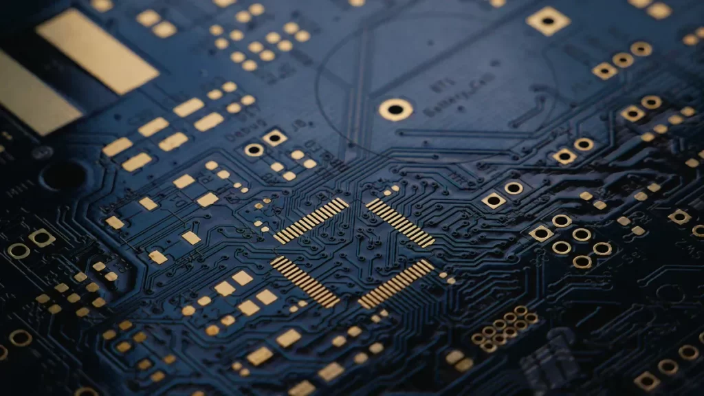
Components of a Printed Circuit Board
Layers of a PCB (Substrate, Copper Layer, Solder Mask, Silkscreen)
A PCB has many layers, each with a job to do. These layers work together to make the board function well. Here’s a simple explanation of the main layers:
Layer | Description |
|---|---|
Substrate | The base layer, usually fiberglass (FR4), gives strength and insulation. |
Copper Layer | A thin copper sheet that carries electricity. It can have one, two, or many layers. |
Solder Mask | A green coating that protects copper lines and stops short circuits. |
Silkscreen | Adds labels and symbols to help identify parts and connections. |
These layers are the base of every PCB. They make it strong, conductive, and easy to assemble.
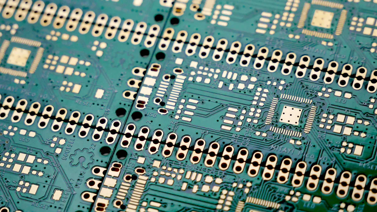
Key Features (Traces, Pads, Vias, Components)
When you look at a PCB, you’ll see important parts that make it work:
Traces: Thin copper lines that move electricity between parts. They connect everything on the board.
Pads: Small copper spots where parts are attached by soldering.
Vias: Tiny holes that link different layers of the board. They can be Thru-Hole, Blind, or Buried, depending on their use.
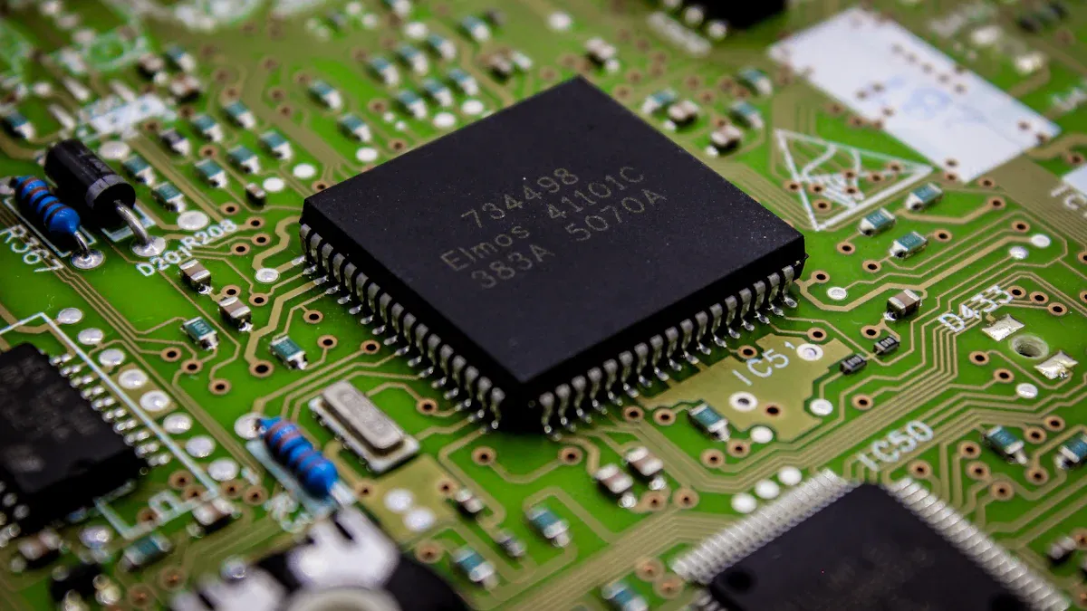
Components: These include resistors, capacitors, and chips, which perform specific tasks on the board.
Each of these features helps the PCB work properly and reliably.
Common Components Used in PCBA Design (Resistors, Capacitors, ICs)
In PCBA design, some parts are very important for making electronics work. Here are the most common ones:
Resistors: These control how much electricity flows and turn extra energy into heat. They have color bands to show their resistance value.
Capacitors: Capacitors hold and release energy. They help keep voltage steady and clean up signals. Radial capacitors are a popular type.
Transistors: These act like switches or boosters for electric signals. Common types are NPN, PNP, and FETs.
These parts, along with the PCB design, make modern devices work smoothly and dependably.
The PCB Design Process
Step 1: Schematic Design
The first step in PCB design is making a schematic. This is like a map showing how parts connect. Special software helps draw this map. To make a good schematic, follow these tips:
Schematic Design Aspect | Description |
|---|---|
Page size | Pick a page size, like A4, to fit your design. |
Page naming convention | Use clear names like A_Block or B_Power Supply for sections. |
Symbol creation | Place symbols on a grid to connect them correctly. |
Notes/comments/revision history | Write notes and keep a history of changes for easy updates. |
Use clear symbols and text so the schematic is easy to read. Arrange parts neatly and avoid crowding to make the design simple and useful.
Step 2: Component Placement
Once the schematic is ready, place parts on the PCB. This step affects how well the board works. Good placement helps with power flow, heat control, and building the board. Here are some tips for placing parts:
Group similar parts together to make connections easier.
Keep parts that don’t like heat away from hot areas.
Place parts in the same direction to avoid mistakes.
Leave space for copper lines and testing tools.
For example, putting power parts close together can make routing easier and improve heat control. A well-planned layout makes devices more reliable.
Step 3: Routing and Trace Design
Routing links parts on the PCB with copper lines. This step needs care to keep signals strong and the board working well. Follow these routing tips:
Description | |
|---|---|
Power Layer Routing | Use power layers for slow signals to save space. |
Impedance-Controlled Traces | Follow spacing rules to keep trace impedance correct. |
Layer Utilization | Combine power and signal layers to save room and improve design. |
Avoid sharp turns in copper lines, as they can weaken signals. Good routing helps your PCB work better and last longer.
Step 4: Design Rule Check (DRC) and Validation
Design Rule Check (DRC) makes sure your PCB design follows rules. These rules include trace width, spacing, and via sizes. Running DRC helps find mistakes before production starts. This saves both time and money.
Tip: Run DRC several times to catch all issues early.
Why is DRC important?
It spots problems that could cause production failures.
It fixes design mistakes early, avoiding expensive changes later.
Validation works with DRC to check if the design works right. For example, you can test how signals move through the board. This helps find delays or interference. Together, DRC and validation ensure your PCB will work properly.
Step 5: Preparing Manufacturing Files (Gerber Files)
After passing DRC and validation, create manufacturing files. These files, called Gerber files, tell manufacturers how to make your PCB. They act like a detailed map for production.
Gerber files include:
Copper lines and pads for electrical connections.
Solder mask layers to stop short circuits.
Silkscreen layers with labels for parts.
Drill hole patterns for vias and mounting holes.
Board size and shape for cutting.
These files also guide the UV process to build PCB layers. They even show surface finishes and layouts for mass production.
Note: Always check Gerber files carefully before sending them out. Mistakes in these files can ruin the boards.
By making clear and correct Gerber files, you help production go smoothly. This step is key for creating high-quality PCBs.
Why PCB Design Matters in Electronics
Makes Devices Work Well and Last Long
PCB design is key to making electronics work and last. Devices like phones and smart gadgets need good PCBs to perform well. A smart PCB layout helps parts connect and work smoothly together.
Good design, like placing parts wisely and routing signals well, makes devices reliable. For example, small PCBs in gadgets handle tough tasks without breaking or overheating.
Trend/Metric | What It Means |
|---|---|
Smaller Designs | Tiny, efficient systems in gadgets push PCB design forward. |
Industry Needs | Cars and healthcare tools need advanced PCBs for better use. |
New Tech | Flexible and HDI PCBs meet the need for compact, modern designs. |
Helps Create Small and Smart Devices
Today’s gadgets need to be small and powerful. PCB design helps by arranging parts smartly and using new tech like flexible PCBs. These PCBs shrink device size but keep them working well.
5G phones use flexible PCBs to save space and keep signals strong.
Space tools use light PCBs to connect parts safely in space.
Cars use small PCBs for safety systems that work better.
HDI and multi-layer boards pack more features into tiny spaces. These designs make gadgets faster, lighter, and smarter.
Drives New Technology
PCB design helps invent new tech. Better materials and methods have changed electronics over time. For example, new PCB materials improve how devices work and last. Conductive inks make electronics more flexible.
Wearables use rigid-flex PCBs to stay light and fit the body.
Car PCBs handle stress and fit odd shapes for better use.
PCB design has made smart tech possible. From phones to space tools, PCBs keep pushing what technology can do.
Lowers Production Costs and Mistakes
PCB design is very important for cutting costs and avoiding errors. By planning the board layout carefully, you can stop expensive problems during production. A good PCB design helps factories make boards faster and with fewer mistakes.
Here’s how PCB design saves money and reduces errors:
Better Material Use: A smart design uses less material, saving money. Multi-layer PCBs combine many functions into one board, so fewer boards are needed.
Stops Mistakes Early: Tools like Design Rule Check (DRC) find errors early. This avoids problems like wrong trace sizes or parts overlapping, saving time and money.
Easier Assembly: A neat layout makes assembly simpler. Machines can place parts quickly and correctly, cutting labor costs and human mistakes.
Simpler Testing: Adding test points helps find problems during production. Faulty boards can be fixed before they are sold.
Tip: Always review your Gerber files before sending them to the factory. Even a tiny mistake in these files can cause big delays and extra costs.
Advantage | Effect on Costs and Errors |
|---|---|
Smaller Design | Uses fewer materials, lowering production costs. |
Machine Assembly | Speeds up work and reduces human mistakes. |
Early Problem Detection | Avoids costly fixes and ensures better quality. |
By focusing on smart PCB design, you save money and make sure your products are high quality. This helps you stay competitive and deliver reliable devices.
PCB design is the base of today’s electronics. It plans how parts like resistors and capacitors connect to make devices work well. Its layers, features, and steps all help create small and efficient systems.
PCB design helps make smaller and smarter gadgets.
Design automation improves circuits and speeds up production.
Understanding PCB design shows how it shapes future technology.
FAQ
What software do you need for PCB design?
Software like Altium Designer, Eagle, or KiCad is useful. These programs help make schematics, layouts, and files for production. Some also let you test designs before making the PCB.
How do you choose the right PCB material?
Pick materials based on what your device needs. FR-4 works for most devices. Polyimide or Rogers materials are better for flexible or high-speed designs. Match the material to how strong and reliable your device must be.
What is the difference between single-layer and multi-layer PCBs?
Single-layer PCBs have one copper layer for connections. Multi-layer PCBs stack copper layers for complex designs. Multi-layer boards fit small gadgets like phones. Single-layer boards work for simpler electronics.
Why are Gerber files important?
Gerber files tell factories how to make your PCB. They show copper lines, solder masks, and drill holes. Bad Gerber files can cause mistakes or delays during production.
How can you avoid mistakes in PCB design?
Follow design rules and check your work often with DRC tools. Place parts carefully and route traces correctly. Use simulation tools to test your design early.
Tip: Always review your design and files before production to save money and time.
See Also
Understanding PCBA Services and Their Importance in Electronics
Defining PCBA and Its Significance in Electronic Manufacturing
Exploring PCBA: Its Definition and Importance in Electronics