
A circuit board is very important for modern electronics. It links different parts so devices can work well. About 70% of circuit boards help with consumer electronics, computers, and communication. You can find circuit boards in things like smartphones, tablets, and TVs. Learning how to make a circuit board can help you create your own electronic projects. This will improve your skills in this important area.
Key Takeaways
Knowing about circuit board parts like resistors, capacitors, and transistors is very important. It helps with good design and function.
Picking the right materials, like FR-4 substrates and pure copper foil, makes your circuit board work better and last longer.
Follow a clear assembly process. This includes designing the circuit, preparing the PCB, placing parts, and soldering. This will help you build it successfully.
Testing your circuit after you build it is very important. Use ways like looking closely and in-circuit testing to find and fix problems.
Start your own circuit board project today! Collect your materials and enjoy making working electronic devices.
Circuit Board Components
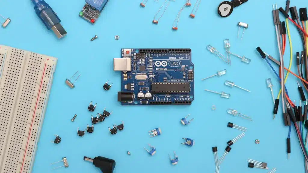
When you make a printed circuit board (PCB), knowing the important parts is key. Each part has a special job in how your circuit works. Let’s look at some common parts you will see.
Resistors
Resistors are important parts that control electrical current in your circuit. They add resistance, which helps manage how electrical charges move. Here are some main jobs of resistors:
They control how much electrical current flows in a circuit.
Resistors create a voltage drop, so parts get the right voltage.
They lower current when added in series, acting like valves for electron flow.
The most common types of resistors used in circuit board making are:
Resistor Type | |
|---|---|
Carbon Composition Resistor | < 1Ω to several MΩ |
Film Resistor | Up to > 10MΩ |
Wire-wound Resistor | Various resistance ratings |
Semiconductor Resistor | High precision, varies |
Knowing how resistors work is important for good circuit design. They help make sure everything works well, even when used a lot.
Capacitors
Capacitors are another key part in PCBs. They store electrical energy and release it when needed, acting like temporary power banks. Capacitors also help control voltage levels and filter out noise. Here’s how they help circuits work:
They soak up voltage spikes and release energy during drops.
Capacitors filter out high-frequency noise, giving cleaner signals.
The main types of capacitors you might use are:
Type of Capacitor | |
|---|---|
Ceramic Capacitors | 1pF to 1μF |
Electrolytic Capacitors | 1µF to 47mF |
Film Capacitors | 1pF to 10μF |
In many circuits, putting a capacitor across the power and ground pins reduces noise that could affect integrated circuits (ICs).
Inductors
Inductors are important for managing electromagnetic interference (EMI) and storing energy. They keep energy in magnetic fields and help filter signals. Here are some common uses of inductors:
Power Supply Circuits: Used for voltage control and filtering.
Signal Filtering: Helps keep signals clean in devices like radios and TVs.
Impedance Matching: Adjusts impedance in high-frequency circuits.
Inductors are usually measured in microHenries (μH) and nanoHenries (nH). They are important for making sure electronic designs work well.
Transistors
Transistors are basic parts that allow amplification and switching in electronic circuits. They can boost weak signals and control large currents. Here are some main jobs of transistors:
Amplification: They make small input signals into larger output signals.
Switching: Transistors act as switches to control if circuits are on or off.
Voltage Regulation: They keep a steady output voltage in circuits.
The main types of transistors you might see are:
Type of Transistor | Main Function |
|---|---|
Low-noise amplification transistors | Amplifying weak signals with little added noise. |
Switching transistors | Control the on/off state of circuits. |
Darlington transistors | Provide high current and power gain for big current needs. |
Transistors are key to modern electronics, allowing for complex circuit designs.
Diodes
Diodes are important for changing current and protecting circuit boards. They let current flow one way and block it the other way. Here’s how diodes work:
They change alternating current (AC) to direct current (DC).
Diodes protect against reverse current, stopping damage from wrong connections.
Common types of diodes include:
Type of Diode | Voltage Rating (Typical) | |
|---|---|---|
Signal Diodes | Low-current uses like signal changing. | Low voltage |
Power Diodes | High-current uses in power supplies. | High voltage |
Schottky Diodes | Low forward voltage, used in high-frequency uses. | Low forward voltage |
Diodes are key for stable and efficient energy delivery in many uses.
Transformers
Transformers help change voltage and isolate circuits. They move power between circuits without direct electrical connections, keeping things safe. Here are some common uses of transformers:
Type of Transformer | Power Ratings | |
|---|---|---|
Standard Power Transformers | AC/DC conversion and voltage adjustment | Various power ratings |
Pulse Transformers | Sending electrical pulses in digital communication systems | Moderate power ratings |
Transformers are important for protecting equipment from voltage spikes, ensuring safe operation in different electrical settings.
Knowing these parts will help you design and build good printed circuit boards. Each part has its own job, and together they make working electronic devices.
Materials for PCBs
When you make a printed circuit board (PCB), the materials you choose are very important. They affect how well your PCB works and how long it lasts. Each material has a special job to help your PCB work right.
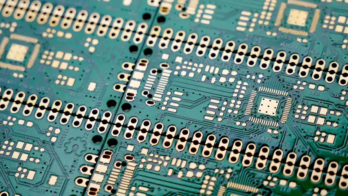
PCB Substrates
The substrate is the base of your PCB. It gives support and keeps electricity from leaking. Here are some common substrate materials:
FR-4 (Flame Retardant 4): This is the most popular substrate. It has great electrical insulation and strength. But, it doesn’t handle heat well for high-frequency uses.
Polyimide: This material is flexible and can handle heat well. It is often used in aerospace but costs more.
PTFE (Polytetrafluoroethylene): This material works well at high frequencies and has great insulation. It is best for RF uses, but it is also pricier.
Metal Core PCBs: These are important for places that need to get rid of heat, like LED lights and high-power electronics.
The dielectric properties of these substrates, like dielectric constant and dielectric loss, are very important for keeping signals clear, especially in high-frequency systems.
Copper Foil
Copper foil is key for making paths on your PCB. It helps with electrical flow, making sure connections between parts are stable. The usual thickness of copper foil in PCBs is between 35 and 70 micrometers, with about 99.9% purity. This high purity helps with reliable electrical performance.
Copper foil is a thin layer of copper that sticks to a substrate to create paths or pads on a printed circuit board.
Solder
Solder connects parts to the PCB. The type of solder you use affects how strong these connections are. Common types include:
Lead-Based Solder: Melts at about 183°C.
Lead-Free Solder: Melts between 217-220°C.
High-Temperature Solder: Melts at 221°C.
Choosing the right solder makes sure joints are strong enough to handle heat changes and stress.
Metal-Core Materials
Metal-core materials, like aluminum, are great for managing heat. They get rid of heat better than regular fiberglass boards. This is very important in high-power uses, where too much heat can harm parts. Metal-core PCBs have many benefits:
Stronger structure
Smaller design
These materials help keep devices that produce a lot of heat working well.
How to Make a Circuit Board: Assembly Steps
Making a circuit board has several important steps. Each step is vital for your PCB to work well. Let’s break down the assembly process into easy parts.
Designing the Circuit
The first step in making a circuit board is to design the circuit. You need to follow these key steps:
Know the electrical parameters.
Make the schematic.
Use a schematic capture tool for your PCB layout.
Design your PCB stackup.
Set design rules and requirements.
Place your components.
Add drill holes.
Route the traces.
Add labels and identifiers.
Create design/layout files.
You can use different software tools for this, like:
Allegro PCB Designer
Altium Designer
Autodesk EAGLE
KiCad EDA
These tools help you see your circuit and make sure everything fits together right.
Preparing the PCB
Before placing components, you must prepare the PCB. Good preparation affects how well your final circuit board works. Follow these steps:
Workspace Setup: Choose a clean, bright workspace with good airflow.
Tool Readiness: Make sure all needed tools are ready, like soldering irons, tweezers, and solder wire.
Component Verification: Check that all components are good and compatible.
PCB Inspection: Look over the PCB for cleanliness and proper pad and trace alignment.
Solder Mask Examination: Make sure the solder mask covers the right areas.
Doing these steps ensures a secure PCB and makes it easier to install your components.
Placing Components
Now it’s time to put the components on your PCB. Here are some best practices to follow:
Best Practice | Description |
|---|---|
Automated Placement | Use pick-and-place machines to reduce errors and speed up production. |
High-Speed Signal Integrity | Place sensitive components near their circuitry to shorten trace lengths. |
Thermal Management | Keep heat-generating components away from sensitive parts. |
Grouping Components | Put related components together to make routing easier. |
Make sure component markings are clear and consistent. Avoid long trace lengths to keep signal quality, especially for high-speed signals.
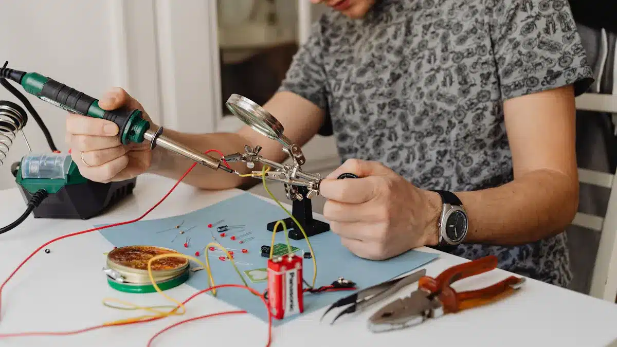
Soldering Techniques
Soldering is a key step in putting your circuit board together. Here are some good soldering techniques:
Hand Soldering
Surface Mount Technology (SMT)
Wave Flow Soldering
Selective Soldering
Each technique has its uses. For example, SMT is great for small designs, while wave soldering is common for through-hole parts.
To solder well, keep your workspace clean and properly tin the soldering iron tip. Use the right amount of heat to avoid damaging parts.
Testing the Circuit
After assembly, testing your circuit is very important. Here are some common methods:
Visual Inspection: Look for solder problems and check component orientation.
In-Circuit Testing (ICT): Use automated testing for thorough fault coverage.
Swap and Test: Change suspected faulty components with known good ones.
You might find issues during testing, like soldering mistakes or wrong component placements. Use a multimeter in continuity mode to find hidden shorts. Write down your tests to help with diagnostics.
By following these steps, you can successfully make a circuit board that works as planned. Each part of the assembly process helps the overall performance and reliability of your PCB.
In this blog, you learned about key parts like resistors, capacitors, and transistors. You also looked at important materials like PCB substrates and copper foil. Each part is very important for making your circuit board work.
Now, collect your materials and begin your own circuit board project! 🛠️ It feels great to create something that works. Jump into the world of electronics and have fun building your own devices!
FAQ
What are PCB standoffs and spacers?
PCB standoffs and spacers help hold up your circuit board. They keep space between the PCB and the case. This helps air flow and stops dirt from getting in. These parts also make the assembly stronger.
Why are insulators important in circuit boards?
Insulators stop unwanted electrical connections between parts. They keep dirt away and make sure signals stay clear. Using good insulators helps keep your circuit design working well.
How do I choose the right solder for my PCB?
Pick solder based on what your project needs. Lead-based solder melts at lower temperatures. Lead-free solder is better for the environment. Make sure the solder is strong enough for reliable connections.
What materials improve the strength of my PCB?
Using materials like FR-4 and metal-core substrates makes your PCB stronger. These materials give high strength and help manage heat. This ensures your circuit board works well in different situations.
How can I protect my circuit board from contamination?
To keep your circuit board safe from dirt, use good enclosures and apply conformal coatings. These methods protect sensitive parts and keep electrical connections working well for a long time.
See Also
Streamlined PCBA Solutions for Your Electronics Projects
Crucial Advice for Selecting the Perfect PCBA Board
An In-Depth Overview of PCBA Production Processes