You might wonder about the difference between a printed wiring board and a pcb. A printed wiring board, sometimes called a printed wire board, shows only the wiring patterns on a rigid surface. When you add electronic parts to a pwb, it becomes a pcb. The term pcb stands for printed circuit board and has become the standard in industry literature over the past 20 years. People once used printed wiring board or printed wire board more often, but now you will mostly see pcb or pwb used. The change shows how much technology has advanced.
Key Takeaways
Printed wiring boards have only wiring patterns. Printed circuit boards have wiring and electronic parts. PWBs are simple and cheap. They are good for basic circuits. PCBs can handle complex designs. They give high performance and work with advanced electronics. PCBs use many layers and machines to put them together. This helps signals stay strong and makes them more reliable than PWBs. Pick the right board for your project. Use PWBs for easy jobs. Use PCBs for fast or tough devices. Follow industry rules and choose good materials. This helps your circuit board work well and last longer.
Printed Wiring Board vs. Printed Circuit Board
Definitions
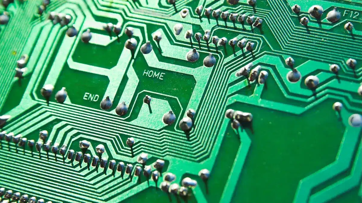
You may see the terms printed wiring board and pcb used in electronics. These words describe different stages in the life of a circuit board. A printed wiring board, or pwb, is a flat board with only the wiring patterns printed on it. You will not find any electronic parts attached to a printed wiring board. People sometimes call it a printed wire board. This board acts as the base for building more complex circuit boards.
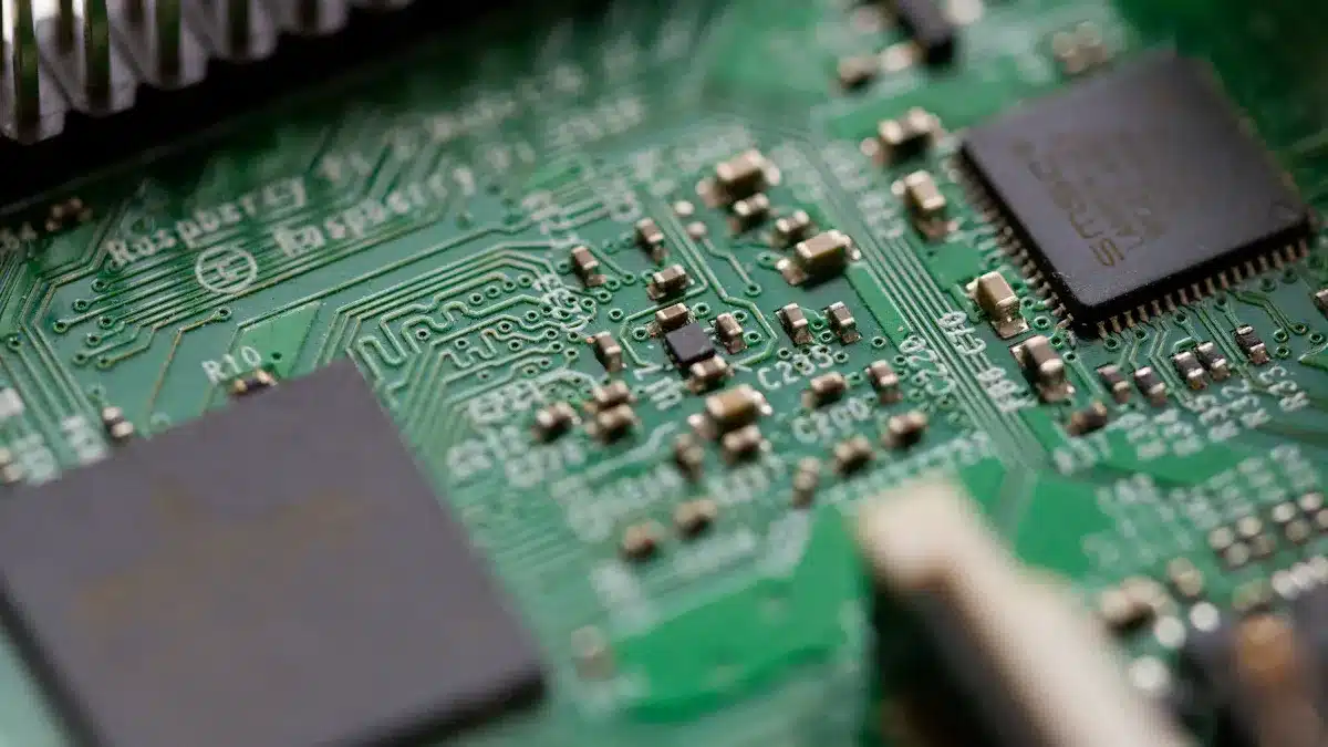
A pcb, or printed circuit board, is a circuit board that has both the wiring and the electronic components mounted on it. When you add resistors, chips, and other parts to a pwb, it becomes a pcb. The pcb connects all the parts together so they can work as a complete system. Most people now use the term pcb instead of printed wiring board or printed wire board. The word pcb covers both the wiring and the finished, working circuit board.
Key Differences
You will notice several key differences between a printed wiring board and a pcb. The main difference comes from what each board includes. A printed wiring board only has the wiring patterns. A pcb has both the wiring and the electronic parts.
You can see more differences in the table below:
Aspect | Printed Wiring Board (PWB) | Printed Circuit Board (PCB) |
|---|---|---|
Structure | Conductive wires printed directly on a non-conductive base like fiberglass. The design stays simple. | Multi-layered copper tracks with insulating layers. The design can be very complex. |
Complexity | Simpler and best for basic circuit boards. | Supports dense and advanced circuit board designs. |
Performance | Works for basic functions but may not handle high speeds or frequencies well. More likely to have interference. | Handles high speeds and frequencies. Gives better signal quality and less interference. |
Manufacturing | Uses a simple printing method on the board. | Needs several steps like etching, drilling, and layering. |
Cost | Costs less because of the simple design and process. | Costs more due to advanced design and extra steps. |
You will often use a printed wiring board when you need a simple circuit board for basic tasks. A pcb works better for complex electronics, like computers or smartphones. The pcb can have many layers and support more parts. Most modern circuit boards use the pcb design because it gives better performance and reliability.
Note: You may still see the term pwb in older documents or in some industries, but pcb is now the standard word for most circuit boards.
You should choose the right term based on what you need. If you talk about a bare board with only wiring, use printed wiring board or pwb. If you mean a finished board with all the parts, use pcb or printed circuit board. This helps you avoid confusion and makes your work clear to others.
PCB and PWB Design Complexity
Wiring Patterns
When you look at wiring patterns, you see big differences between a pwb and a pcb. A pwb usually has simple wiring. Most pwb designs use single-sided boards, so you find all the wiring on one side. This makes the layout easy to follow and repair. You often use a pwb for basic circuits or prototypes.
A pcb, on the other hand, can have many layers. You might see double-sided or even multilayer boards in a pcb. This lets you fit more connections and parts into a small space. You need to plan trace routing carefully in a pcb. The width and spacing of each trace matter a lot. If you do not plan well, you might get signal problems or power loss. In a pcb, you also use power and ground planes to keep voltage steady and avoid noise. High-speed pcb designs need controlled impedance and good grounding to keep signals clean.
Factor | PWB | PCB |
|---|---|---|
Number of Layers | Usually single-sided | Single, double, or multilayer |
Trace Routing | Simple, easy to follow | Complex, needs careful planning |
Power Delivery | Basic | Uses planes for stable power and ground |
Signal Integrity | Less important | Very important, especially for high-speed circuits |
Tip: If you want a simple project, a pwb works well. For advanced electronics, you need the extra features of a pcb.
Component Integration
You will also notice big changes in how you add parts to a pwb versus a pcb. On a pwb, you often solder parts by hand. You might use point-to-point wiring, which lets you change things easily. This method works for small projects or when you want to test ideas. It takes more time and can lead to mistakes if you are not careful.
A pcb uses automated machines to place and solder parts. You see methods like reflow soldering or wave soldering in pcb assembly. These machines work fast and make fewer mistakes. You can fit more parts on a pcb, and the layout stays neat and compact. This makes a pcb the best choice for mass production and complex devices.
Aspect | PWB | PCB |
|---|---|---|
Component Integration | Manual soldering, flexible wiring | Automated soldering, dense layouts |
Application | Prototyping, small runs | Mass production, advanced electronics |
You save time and get better quality with a pcb. If you only need a few boards or want to change your design often, a pwb gives you more freedom. For most modern products, you will use a pcb because it supports complex circuits and high reliability.
Materials and Construction of Circuit Boards
Substrate Materials
The base of a circuit board is called the substrate. The substrate is very important for how the board works. There are different types of substrates. Each type has its own good points. FR4 is the most common one. FR4 is made from glass fibers and epoxy resin. It gives strong support and keeps electricity safe. FR4 works well for most electronics you use every day.
Some boards need to handle more heat or power. For these, people use insulated metal substrates or ceramic materials. IMS has a metal core like aluminum or copper. This helps move heat away from the board. Ceramic substrates, like aluminum nitride, can handle a lot of heat. They work well in tough places. Flexible circuit boards use polyimide. Polyimide lets you bend or fold the board without breaking it.
Here is a table that lists the main substrate materials and what they do:
Substrate Material | Key Properties | Performance Impact |
|---|---|---|
FR4 | Good insulation, strong, cost-effective | Reliable for most uses, not for high heat or frequency |
IMS (Aluminum/Copper) | Excellent heat dissipation | Best for high-power and LED circuit boards |
Ceramic | High thermal conductivity, heat resistant | Works in extreme conditions, high-frequency circuits |
Flexible (Polyimide) | Bendable, durable, lightweight | Used in wearables and foldable circuit boards |
High-Frequency (Rogers) | Low signal loss, stable at high frequencies | Keeps signals clear in fast circuit boards |
The price of your board depends on the substrate you choose. FR4 is the cheapest and works for most things. If you need special features, you will pay more. Rogers and ceramic cost more. Thicker boards and extra copper also make the board cost more.
Tip: Pick your substrate based on what your board needs. Use FR4 if you want to save money. For better performance, try IMS, ceramic, or high-frequency materials.
Layer Structure
The number of layers in a board changes how well it works. You can make a board with one layer or many layers. Single-layer boards are simple and easy to build. People use them for basic electronics.
Double-layer boards let you add more connections. You can put traces on both sides of the board. For harder projects, you might use multilayer boards. These have four or more layers. This helps you fit more circuits in a small space. It also helps stop interference.
High-frequency boards use special layer structures. The most common ones are:
Microstrip: Traces are on the top layer with a ground plane below.
Stripline: Traces are between two ground planes inside the board.
Grounded Coplanar Waveguide (GCPW): Traces have ground on both sides and below.
These structures help keep signals clean and stop noise. When you design a board, think about how many layers you need. Also think about what kind of signals you will use.
Note: More layers and special structures make your board stronger. But they also make it cost more and harder to build.
Manufacturing Process
PWB Fabrication
To make a pwb, you first design a simple wiring pattern. You can use easy software or draw it by hand. You pick cheap materials like phenolic or epoxy resins. Then, you put on a photoresist layer and shine UV light to make the wiring pattern. Next, you do etching to take away extra copper and leave the wiring. After that, you drill holes for through-hole parts. Plating helps the wiring connect, but this step is simple for a pwb.
You add a basic solder mask to keep the wiring safe. A simple silkscreen shows where to put the parts. Most pwb building uses hands or simple machines for putting parts on and testing. Quality checks, like looking at the board and testing with electricity, help you find mistakes early. Making a pwb uses less water and fewer chemicals than making a pcb, so it is better for the environment.
Fabrication Step | Printed Wiring Board (PWB) |
|---|---|
Design and Layout | Simpler designs, often manual or basic software |
Material Preparation | Cost-effective substrates like phenolic or epoxy resins |
Printing Pattern | Photoresist applied, UV exposure through mask |
Etching | Straightforward etching to remove unwanted copper |
Drilling | Basic drilling for through-hole components |
Plating | Basic plating to ensure connectivity |
Solder Mask Application | Basic solder mask to protect wiring pattern |
Silkscreen Printing | Simple silkscreen for component ID |
Assembly and Testing | Manual or semi-automatic component placement, basic testing |
Tip: Always check your design and materials before you start making the board. This helps you stop big mistakes.
PCB Assembly
Making a pcb is harder and needs more steps. You start with a detailed design using CAD software. This makes Gerber files that tell machines what to do. You use strong materials like FR4 to make the board last longer. The process has careful etching, drilling, and copper plating for many layers.
For pcb assembly, machines put and solder parts on the board. The main ways are Surface Mount Technology (SMT), Through-Hole Technology (THT), and mixed technology. SMT puts small parts right on the board, so the board is small and quick to make. THT puts part leads through holes, which makes big parts stay strong. Mixed technology uses both ways for the best results.
You can have problems when making a pcb. Bad soldering, wrong part placement, or bent boards can make the board not work. You must control heat and electrical noise to keep the board working well. Quality checks are very important. You use Automated Optical Inspection (AOI), X-ray checks, and in-circuit tests to find problems before the board leaves the factory.
Note: Making a pcb uses more water and chemicals than making a pwb. You need to follow safety rules and recycle when you can.
Applications of Printed Circuit Boards
Common Uses
You see printed circuit boards in almost every electronic device you use today. These circuit boards help connect and support all the parts inside your gadgets. You find them in many industries because they are reliable and easy to use. Here is a table that shows where you often find a circuit board and what it does in each field:
Industry | Typical PCB Applications & Characteristics |
|---|---|
Medical | Used in imaging systems, heart monitors, and pacemakers. These circuit boards need high precision and reliability. |
LED Lighting | Help manage heat in LED lights for homes, cars, and computers. Many use aluminum to move heat away from the LEDs. |
Consumer Electronics | Power smartphones, computers, TVs, and home appliances. These circuit boards are small, dense, and must be reliable and low-cost. |
Industrial Equipment | Found in manufacturing tools and measuring devices. These circuit boards must handle vibration, chemicals, and tough conditions. |
Automotive | Used in car entertainment, navigation, and control systems. These circuit boards must resist heat and vibration to keep you safe. |
You can see that pcb technology supports many different needs. In consumer electronics, a pcb makes your devices smaller and lighter. In medical devices, a circuit board must meet strict quality standards. You also find circuit boards in LED lighting, where they help control heat and improve the life of the lights. Industrial and automotive uses need circuit boards that last a long time and work in harsh places. When you look at pwb and pcb applications, you notice that pcb designs allow for more complex and reliable products.
Industry Standards
You need to follow strict rules when you design and build a circuit board. These rules help make sure your pcb works well and lasts a long time. The IPC is the main group that sets these standards for circuit boards. Here are some of the most important standards you should know:
IPC 2221: Sets basic design and performance rules for all circuit boards.
IPC 2222: Focuses on rigid pcb design, including material choice and layout.
IPC 4101: Lists what materials you can use for pcb layers.
IPC 2152: Tells you how much current copper traces can carry.
IPC 4761: Gives tips for protecting vias to keep your circuit board reliable.
IPC 6012: Sets quality and reliability standards for finished circuit boards.
IPC-A-600: Explains how to judge the quality of a pcb and sorts them into classes.
IPC 7351: Provides rules for making footprints for surface mount parts.
IPC-1752A: Covers how to report and manage materials in your circuit board.
Tip: Following these standards helps you make sure your pcb meets safety, quality, and performance needs in any industry.
These standards guide you from the first design to the final test of your circuit board. When you follow them, you help make sure your circuit boards are safe, reliable, and ready for use in any device.
Summary Table of Differences
Quick Comparison
It helps to see how printed wiring boards and printed circuit boards are different. The table below shows both types side by side. This makes it easy to pick the right one for your project.
Aspect | Printed Wiring Boards (PWBs) | Printed Circuit Boards (PCBs) |
|---|---|---|
Single-sided, simple circuits | Single, double, or multilayer; supports complex, dense designs | |
Materials | Lower-cost substrates like phenolic paper, epoxy glass | High-performance materials such as FR-4, polyimide, Rogers |
Manufacturing | Simple steps: photolithography, screen printing, etching | Advanced: laser imaging, inkjet printing, multilayer lamination |
Performance | Good for basic functions, lower signal quality | High signal integrity, controlled impedance, less crosstalk |
Thermal Management | Limited heat handling | Enhanced with metal cores, heat sinks |
Mechanical Stability | Moderate strength, more likely to warp | Strong, resists vibration and thermal changes |
Environmental Resistance | Basic protection, best for mild settings | High resistance to moisture, chemicals, and temperature extremes |
Cost | Lower cost, simple materials and process | Higher cost, advanced features and materials |
Applications | Simple electronics, low part count | Complex, high-performance, aerospace, automotive, industrial systems |
📝 Tip: Pick a PWB if your project is easy or just a test. If you need something fast, strong, or for tough places, use a PCB.
This table is good to check before you start building. PWBs are cheap and work for small jobs. PCBs are better for hard projects and last longer. Knowing these facts helps you choose the best board and not waste money.
PWBs are best for easy, cheap projects.
PCBs are for hard, important jobs.
The right board choice makes your project work well from the beginning.
You have learned the main differences between printed wiring boards and printed circuit boards. Say “PWB” when you mean a board with just wiring. Use “PCB” for a board that has all its parts on it. Most companies like to use “PCB” because it means both the wiring and the parts.
Factor | PWB is simple and single-sided | PCB is complex and multilayered |
|---|---|---|
Design Complexity | Complex, multilayer | |
Basic | High-performance | |
Cost | Lower | Higher |
Pick the right word for your project and who you are talking to.
If you are not sure, look at the rules or ask the company making your board.
Using the correct word helps people understand you and keeps your work easy to follow.
FAQ
What is the main difference between a PWB and a PCB?
You see a PWB as a board with only wiring patterns. When you add electronic parts, it becomes a PCB. Most people now use “PCB” for both the bare board and the finished product.
Can you use a PWB for complex electronics?
You should not use a PWB for complex electronics. PWBs work best for simple circuits. If you need many layers or high performance, you need a PCB.
Why do most companies use the term “PCB” today?
Most companies use “PCB” because it covers both the wiring and the components. The term “PCB” matches modern technology and industry standards.
Are PWBs cheaper than PCBs?
Yes! PWBs cost less because they use simple materials and designs. PCBs cost more since they support advanced features and need extra steps in manufacturing.
How do you choose between a PWB and a PCB?
Think about your project needs.
Use a PWB for basic, low-cost circuits.
Pick a PCB for advanced, reliable, or high-speed electronics.
Tip: Ask your manufacturer if you feel unsure about which board to use.
See Also
Understanding The Main Distinctions Between PCB And PCBA
Unveiling The Lesser-Known Differences Between PCBA And PCB
Analyzing Functional And Structural Variations Of PCBA Versus PCB