In PCB manufacturing, understanding how to produce PCB is crucial. You need different machines and tools for good production. Each part of the process, from design to assembly, requires special equipment. To make PCBs well, you must know how to produce PCB by using the right tools at each step. This knowledge helps you make production easier and maintain high quality.
Key Takeaways
Using the right tools at each step of PCB production makes quality better and speeds up making them.
Good PCB design software and schematic tools help make accurate layouts. They also reduce mistakes early on.
Fabrication machines like etching, drilling, and lamination shape the PCB. These machines must be controlled carefully for the best results.
Assembly machines such as pick-and-place, solder paste printers, and reflow ovens make sure parts are placed and soldered correctly.
Inspection and testing tools like AOI, X-ray systems, and in-circuit testers find problems early. This helps ensure PCBs are reliable.
Overview of PCB Manufacturing Process
Stages of PCB Production
The PCB manufacturing process has many steps. Usually, there are about twenty steps in a normal production cycle. Here’s a quick look at these steps:
Designing the PCB
Checking the design and asking engineering questions
Printing the PCB design
Printing copper for inside layers
Etching the inner layers
Drilling holes
Plating and adding copper
Imaging the outer layer
Etching the outer layer
Checking the outer layer with Automated Optical Inspection (AOI)
Applying the solder mask
Adding silkscreen and surface finish
Finishing the PCB
Testing for electrical reliability
Profiling and cutting out
Checking quality and visual inspection
Packaging and delivery
Each step is important to make sure the final product is good quality.
Importance of Equipment
The equipment you pick affects the quality and speed of each step in the PCB manufacturing process. For example, using advanced etching machines helps remove unwanted copper accurately. This is important for making correct circuit patterns. Also, automated drilling machines make precise holes for vias and component leads. This ensures your PCB works well.
Automation and robots also speed up production and lower mistakes. Machines like pick-and-place units and solder paste printers make assembly faster. This leads to quicker turnaround times and better yields. Additionally, careful inspection methods, like Automated Optical Inspection (AOI), make sure your PCBs meet design and industry standards. This careful checking helps guarantee the reliability and overall quality of your manufactured PCBs.
PCB Design Equipment
In PCB production, the design phase is very important. You need the right tools to make good designs. Two main types of equipment are key in this stage: PCB design software and schematic capture tools.
PCB Design Software
PCB design software helps you make layouts and schematics for your boards. Here are some popular tools used in the industry:
Altium Designer: This software has a complete design environment. It includes features for schematic capture, PCB layout, and 3D modeling. Many professionals in aerospace and automotive fields like it.
Siemens PADS: This tool is liked by small and mid-sized companies. It offers customizable layout tools and works well with mechanical CAD.
Cadence Allegro: Known for handling complex designs, this high-end suite has advanced routing and validation tools. It is good for large electronics companies.
EAGLE: This easy-to-use software is popular with hobbyists and small businesses. It has integrated schematic and layout tools, making it simple for beginners.
OrCAD: This flexible tool is great for small to medium teams. It offers schematic capture and signal integrity analysis.
Choosing the right software depends on your project’s complexity, budget, and team size. For big projects, Altium, Cadence Allegro, and Siemens PADS are often chosen. For smaller or budget-friendly projects, EAGLE and KiCad are great options.
Schematic Capture Tools
Schematic capture tools let you create circuit diagrams. They help you see how components connect on your PCB. Top tools in this area have several important features:
Integrated SPICE simulation: This feature lets you check circuit functionality before moving to layout.
Dynamic synchronization: Changes in the schematic automatically update the PCB layout, keeping everything consistent.
Error detection: These tools find common mistakes, like opens and shorts, early in the design process.
Using these tools improves your design accuracy and efficiency. They lower the risks of manufacturing errors. By investing in good PCB design software and schematic capture tools, you build a strong base for successful PCB production.
PCB Fabrication Equipment
In the PCB manufacturing process, fabrication equipment is very important. This equipment changes your designs into real printed circuit boards. Three main types of fabrication machines are needed: etching machines, drilling machines, and lamination machines.
Etching Machines
Etching machines take away unwanted copper from the PCB surface. This makes the circuit patterns you designed. There are two main types of etching machines: spray systems and immersion systems.
Spray System: This type works faster because of good liquid flow. It is best for fine-line, high-density PCBs, allowing for more production.
Immersion System: This system is slower but gives more even etching over larger areas. It is better for thicker materials and multilayer PCBs.
Type of Etching Machine | Throughput Characteristics |
|---|---|
Spray System | Faster etching speed due to efficient liquid flow; higher throughput suitable for fine-line, high-density PCBs |
Immersion System | Slower etching speed but more consistent over larger surfaces; lower throughput but better for thicker substrates and multilayer PCBs |
When using etching machines, safety and environmental care are very important. Here are some key safety tips:
Wear protective gear like gloves, goggles, and face masks when using etching chemicals.
Work in a well-ventilated area to avoid breathing harmful fumes.
Avoid touching etching chemicals with your skin to prevent irritation and burns.
Dispose of etching chemicals properly according to local rules to prevent harm.
Drilling Machines
Drilling machines make holes in the PCB for components and vias. Modern machines use new technology to ensure accuracy and efficiency. They can work at different speeds, which affects hole quality and production speed.
Drill speed affects hole quality, drill bit life, and cost.
The best drill speed depends on PCB material, hole size, and drill bit type.
Automated speed control systems help keep drilling performance steady.
Modern drilling methods include mechanical drilling and laser drilling.
Drilling Technique | Typical Accuracy Level | Hole Size Capability | Cost Level | Best Application |
|---|---|---|---|---|
Mechanical Drilling | Moderate precision | Low | High-volume, cost-effective production | |
Laser Drilling | High precision | Holes down to 2 mils or 25 microns | High | Micro-scale, multilayer, high-precision boards |
Automated drilling machines, like CNC and laser drills, give consistent hole sizes and accurate alignment. They reduce problems like misalignment and burrs. Manual drilling does not have the same precision and repeatability as automated methods.
Lamination Machines
Lamination machines join multiple layers of material to make a strong PCB. This process needs careful temperature and pressure control. For good lamination of FR-4 materials, keep the temperature between 180°C and 200°C.
High-Tg types may need temperatures closer to 200°C for full curing.
Pressure during lamination usually ranges from 200 psi to 500 psi.
Keeping temperature and pressure in sync is key to avoiding problems like delamination or warping. Controlled temperature changes during heating and cooling help ensure proper resin flow and curing.
Good lamination makes sure of strong bonding and mechanical stability, which are important for the reliability of your PCB.
By knowing and using the right fabrication equipment, you can improve the quality and efficiency of your PCB production process.
PCB Assembly Equipment
In the PCB manufacturing process, assembly equipment is very important. This equipment makes sure that components are placed correctly and soldered well onto the printed circuit board. Three key types of assembly equipment are the pick-and-place machine, solder paste printing machine, and reflow oven.
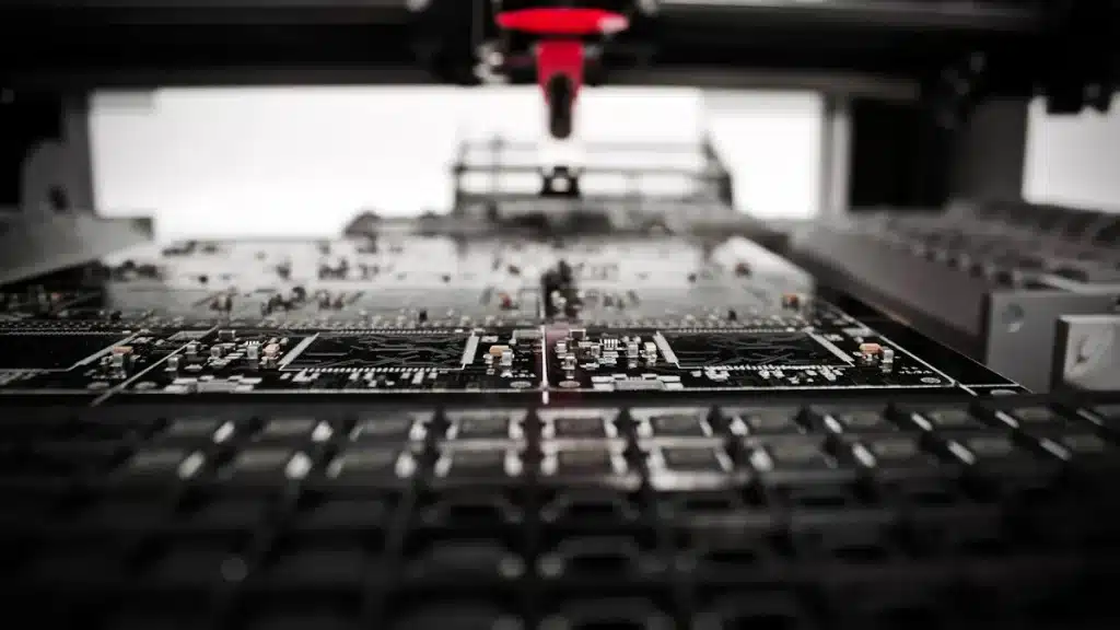
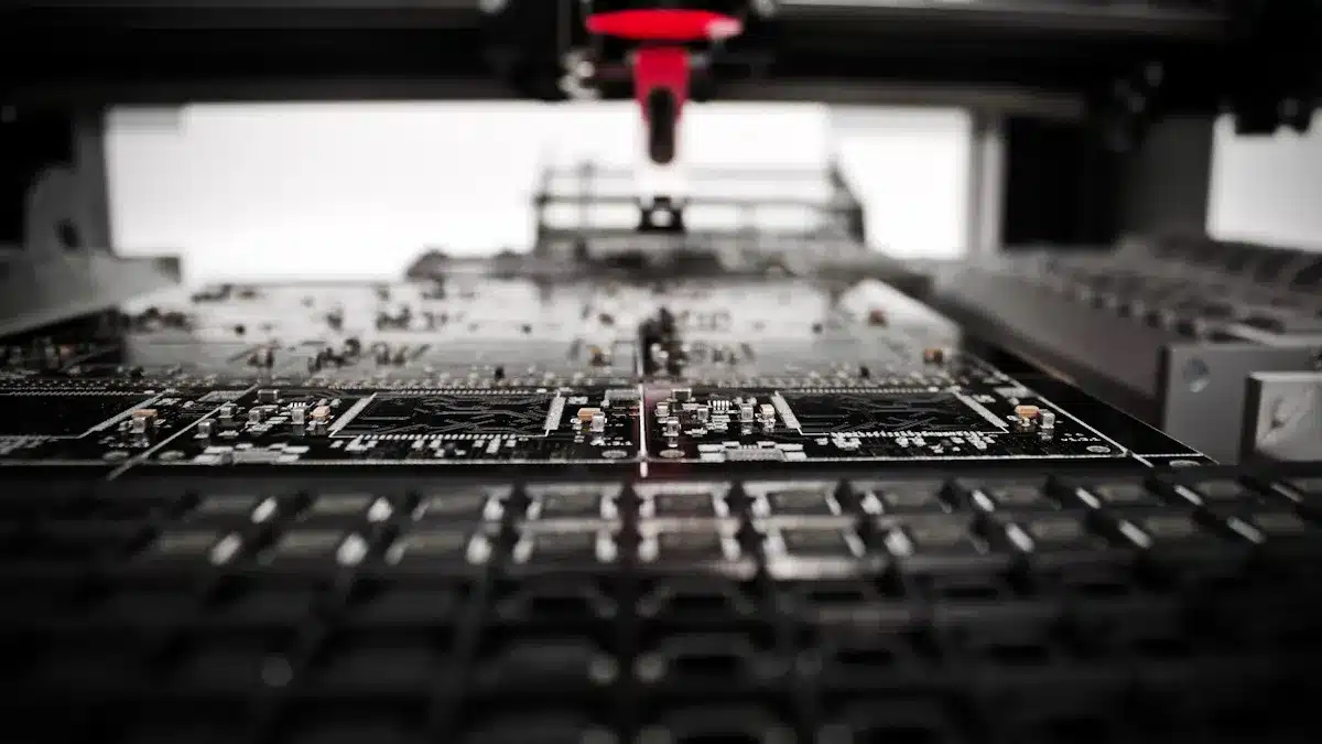
Pick-and-Place Machine
The pick-and-place machine is essential for putting components onto the PCB. This machine uses smart technology to ensure accurate placement. Modern machines can place about 56 components every second. That means they can handle around 200,000 components in one hour. This speed is important for smooth production.
Placement accuracy is also very important. When calibrated right, these machines can be accurate to ±0.025 mm. This precision matters a lot, especially as components get smaller and more crowded. For instance, components can be placed just 0.1 mm apart. The machine’s vision system uses cameras to align components correctly, making sure they fit well on the board.
To manage different sizes and shapes of components, pick-and-place machines use various nozzle types. These nozzles are chosen based on how heavy or delicate the component is. The feeding systems, like tape and tray feeders, present components in ways that work for the machine. This flexibility helps you assemble many types of PCBs quickly.
Solder Paste Printing Machines
Next, the solder paste printing machine puts solder paste on the PCB. This step is key for making strong solder joints. How accurately the solder paste is applied affects the final product’s quality. Important factors for this precision include stencil design, squeegee settings, and printer adjustments.
Stencil design is very important. The size and shape of the stencil openings decide how much solder paste goes on. A good stencil design helps spread the paste evenly, which reduces mistakes. Also, the pressure and angle of the squeegee affect how well the paste moves from the stencil to the PCB.
Regularly cleaning the stencil is also important. Keeping it clean stops paste buildup, which can cause problems like not enough solder or solder bridges. Using inspection systems, like Solder Paste Inspection (SPI), helps you check the quality of the paste application as it happens.
Reflow Ovens
Finally, the reflow oven is where the soldering happens. This machine heats the PCB to melt the solder paste, making strong electrical connections. The temperature during this process is very important for good soldering results.
A typical reflow oven has several zones, each with different temperature ranges. For example, the preheating zone slowly raises the PCB temperature to avoid thermal shock. The reflow zone reaches high temperatures needed to melt the solder. After soldering, the cooling zone helps solidify the joints, making sure they are strong and reliable.
To save energy, manufacturers often use advanced thermal profiling tools. These tools help adjust the oven’s settings to use less energy while still making high-quality solder joints. By optimizing the reflow profile, you can lower energy costs and improve overall production efficiency.
Inspection Equipment
In PCB manufacturing, inspection equipment is very important for quality control. You need good tools to find problems and make sure your boards follow industry rules. Two main types of inspection equipment are Automated Optical Inspection (AOI) and X-ray Inspection Equipment.
Automated Optical Inspection (AOI)
Automated Optical Inspection (AOI) systems use cameras and software to check PCBs for problems. These systems can find over 99% of PCB defects, showing their high accuracy and reliability in spotting manufacturing mistakes. AOI looks for issues like misaligned components, solder bridges, and open circuits.
However, AOI has some downsides compared to manual inspection. Here’s a quick comparison:
Aspect | Automated Optical Inspection (AOI) | Manual Inspection |
|---|---|---|
Flexibility | Needs programming and calibration for each product or defect; takes time to adjust for changes | Naturally flexible; inspectors can quickly adapt to new products or unexpected defects without reprogramming |
Human Judgment | Lacks human intuition and judgment; may miss unusual or complex defects not programmed into the system | Skilled inspectors use experience and intuition to identify complex or unusual defects and make real-time decisions |
Adaptability | Struggles with unexpected defects or new product variations without significant reconfiguration | High adaptability; can handle new defect types and product changes on the fly |
Cost | High initial investment in equipment and software | Lower initial cost but slower and prone to human error |
X-ray Inspection Equipment
X-ray inspection equipment is important for finding hidden problems inside PCBs. This method is great at spotting issues that other inspection methods might miss. For example, it can find solder joint voids, solder bridges, and shorts. X-ray inspection is especially important for checking Ball Grid Arrays (BGAs) and Chip Scale Packages (CSPs), where solder joints are hidden under the package.
The resolution of the X-ray system is key for finding small defects. High-resolution systems can spot tiny voids or cracks that affect PCB reliability. Here’s a summary of defect types detected by X-ray inspection:
Defect Type | Detected by X-ray Inspection (AXI) | Detected by AOI |
|---|---|---|
Open circuits | Yes | Yes |
Solder bridges | Yes | Yes |
Solder shorts | Yes | Yes |
Insufficient solder | Yes | Yes |
Solder voids | Yes | No |
Excess solder | Yes | Yes |
Solder quality issues | Yes | No |
Lifted leads | Yes | Yes |
Missing components | Yes | Yes |
Misaligned/misplaced components | Yes | Yes |
BGA shorts | Yes | No |
BGA open circuit connections | Yes | No |
By using both AOI and X-ray inspection equipment, you can improve the quality control process in PCB manufacturing. These tools help you find defects early, making sure your final products are reliable and meet customer expectations.
Advanced Testing Equipment
In PCB manufacturing, testing equipment is very important. It helps make sure your products are good quality and reliable. Two main types of testing equipment are in-circuit testers (ICT) and flying probe testers. Each type has special benefits that help find problems and improve your PCB assemblies.
In-Circuit Testers
In-circuit testers (ICT) are key for checking each part and connection on a PCB. They measure electrical things like voltage, current, resistance, and capacitance. Here are some main jobs of ICT:
Check if components are placed right and work under test conditions.
Use special tools like test fixtures, probes, and measuring devices.
Find problems like shorts, opens, and missing or wrong components.
The testing steps include putting the PCB in fixtures, loading test programs, and turning on the PCB. ICT can find up to 99% of manufacturing problems. This greatly boosts the quality and reliability of your PCB assemblies. This high level of fault detection helps catch issues early, so you can fix them before functional testing.
Flying Probe Testers
Flying probe testers provide flexibility that traditional bed-of-nails testers can’t offer. Their software-controlled probes can quickly adjust to new PCB designs without needing expensive fixtures. This makes flying probe testers great for low to medium volume production and prototyping. Here are some benefits of flying probe testers:
No custom fixture is needed, which cuts costs.
Probes can reach any test point on the PCB surface.
Flying probe testing usually gets over 95% test coverage in prototype PCB production. This high coverage is because the method is accurate and can reach test points that traditional methods might miss. By using both in-circuit and functional tests, flying probe testers help you check electrical performance effectively.
Both in-circuit testers and flying probe testers are important for keeping high standards in PCB production. They make sure your final products meet customer needs and work reliably.
In conclusion, you need different types of equipment for good PCB production. Important tools are design software, fabrication machines, assembly equipment, inspection systems, and testing devices. Each tool is important for making sure everything is high quality and works well.
Buying advanced manufacturing equipment gives you long-term advantages. You can lower material costs, increase yield rates, and improve product value. Automation also speeds up production and reduces mistakes. By choosing the right tools, you set yourself up for success in the competitive electronics field.
FAQ
What is PCB fabrication equipment?
PCB fabrication equipment includes machines that turn designs into real circuit boards. Important types are etching machines, drilling machines, and lamination machines. Each one is important for making sure the final product is good quality and accurate.
Why is inspection equipment important in PCB manufacturing?
Inspection equipment makes sure your PCBs meet quality standards. Tools like Automated Optical Inspection (AOI) and X-ray inspection find problems early. This helps avoid expensive mistakes and ensures the final product is reliable.
How do pick-and-place machines work?
Pick-and-place machines help put components onto PCBs automatically. They use smart vision systems to make sure everything is placed correctly. This technology makes assembly faster and more precise, which is very important for today’s electronic devices.
What are the benefits of using in-circuit testers?
In-circuit testers check each part on a PCB to see if it works. They find problems like shorts and opens, which helps ensure high reliability. Using ICT can greatly lower manufacturing mistakes and improve overall product quality.
How can I choose the right PCB design software?
Choosing the right PCB design software depends on what your project needs. Think about things like complexity, team size, and budget. Popular choices include Altium Designer for advanced projects and EAGLE for beginners and small businesses.
See Also
Complete Overview Of The PCBA Production Process
Exploring The Methods Behind PCBA Assembly And Manufacturing
Why PCBA Production Skills Matter In Electronic Design
Selecting The Ideal PCB Fabricator To Meet Your Requirements