Choosing the right PCB material means understanding what your project needs and knowing what are circuit boards made of. Designers must select materials that suit how the board will be used, considering factors like performance, reliability, and cost. Common materials include FR-4, high-speed epoxy, polyimide, PTFE, metal core, and FR408HR. Each type is ideal for different printed circuit board designs. The material you choose affects how the board manages heat, stress, and electrical signals. Selecting the right material not only extends the life of circuit boards but also reduces failure rates and helps control costs. The table below highlights how various material properties influence device performance and durability, providing insight into what circuit boards are made of in practical applications.
Factor | Material Property Examples | Impact on Device Performance and Reliability | Cost Considerations |
|---|---|---|---|
Electrical | Dielectric constant, conductivity | Signal quality, current flow, and how well signals move | Material price vs. electrical needs |
Thermal | Glass transition temperature, thermal conductivity | Dissipates heat, prevents overheating, extends board lifespan | Higher Tg and conductivity can increase costs |
Mechanical Strength | Tensile strength, impact resistance, flexural strength | Enhances board durability, prevents damage from stress or drops | Stronger materials may come at a higher price |
Environmental | Toxicity, waste management, compliance | Environmentally safer, better for long-term use | Compliance can add to material and processing costs |
Key Takeaways
Picking the right PCB material depends on what your project needs. You should think about heat, signal quality, strength, and price. FR-4 is the most used and cheapest material. It works well for most electronics. But it is not great for fast signals or high heat. Some special materials like PTFE and polyimide work better for fast signals. They are also good for flexible or tough places. Metal core PCBs are very good at moving heat away. This makes them great for power electronics and LED lights. Use a chart to compare materials. Look at things like dielectric constant, how well it moves heat, and how strong it is. This will help you choose the best PCB material for your project.
Types of Printed Circuit Board Materials
Printed circuit board materials come in many types. Each type has its own special features. Designers need to know about these types to pick the best one. The next parts talk about the most common pcb materials and how they are used. They focus on things like dielectric constant and thermal conductivity. You will also learn where each material works best. This part helps you use the pcb material comparison chart and material comparison chart later in the blog.
FR-4 (Glass Epoxy)
FR-4 is the most popular pcb material. It uses woven fiberglass cloth and epoxy resin. This makes a strong and steady base for many circuit board material types. FR-4 has a dielectric constant from about 3.3 to 4.8. The number depends on the mix and weave. Its thermal conductivity is around 0.3 to 0.4 W/m·K. This means it works well for low or medium power circuits. But it is not great at getting rid of heat.
Note: FR-4 meets UL94-V0 flame rules, so it puts out its own fire.
FR-4 is used in things like consumer electronics and industrial machines. It is also used in multilayer PCBs. It gives good insulation and does not soak up much water. It also has strong arc resistance. Many designers pick FR-4 because it is cheap and strong. But it does not work as well in high-frequency or high-speed jobs. Its low thermal conductivity can be a problem in power electronics.
Low cost and can be used in many ways
Strong mechanical strength
Good electrical insulation
Stops flames and resists moisture
Disadvantages of FR-4:
Does not get rid of heat well
Not good for high-frequency or high-speed jobs
Not bendable for flexible designs
High-Speed Epoxy
High-speed epoxy is better than regular fr4 for fast signals. It gives better signal quality for high-speed uses. These materials have a dielectric constant between 3 and 4. High-speed types are closer to 3 or 3.5. A lower dielectric constant helps stop signal loss. This makes them good for high-frequency and fast digital circuits.
Thermal conductivity in high-speed epoxy helps control heat. The exact number depends on the formula. High-speed epoxy often has a higher glass transition temperature (Tg). Sometimes it is above 170°C. This helps it handle heat during making and use.
High-speed epoxy is used in HDI boards and advanced network gear. It is also used where signal quality is very important. These materials cost more than regular fr-4. They need special ways to make them. But they work much better for high-speed uses.
Comparison Table: FR-4 vs. High-Speed Epoxy
Aspect | FR-4 Material | High-Speed Epoxy |
|---|---|---|
Dielectric Constant | 3.8–4.7 | 3.0–3.5 |
Signal Integrity | Good below 1 GHz | Excellent for high-speed |
Cost | Low | Higher |
Typical Use | General electronics | High-speed, HDI, RF |
Polyimide
Polyimide is special because it is flexible and can take high heat. This material has a dielectric constant from 2.78 to 3.48. The number changes with brand and frequency. Its thermal conductivity is about 0.2 W/m·K. This is lower than fr4. But polyimide can handle very cold and very hot temperatures. It works from -269°C up to 400–500°C.
Polyimide is used in flexible printed circuits and rigid-flex PCBs. It is also used in electronics that face tough conditions. You can find it in aerospace, cars, medical devices, and foldable gadgets. Polyimide is strong and resists chemicals. It also keeps out water and solvents. This makes it a good pick for hard jobs.
Benefits of Polyimide:
Strong and flexible
Resists chemicals and water
Good electrical insulation
Common Applications:
Aerospace and defense electronics
Car control systems
Medical devices
Wearable and foldable electronics
PTFE (Teflon)
PTFE, or Teflon, is used for high-frequency and fast jobs. Its dielectric constant is very low, from 2.0 to 2.1. It stays steady even when the frequency changes. PTFE’s loss tangent is very low. This means signals move with almost no loss or change. PTFE is great for RF, microwave, and 5G circuits.
PTFE’s thermal conductivity is about 0.3 W/m·K. So, it does not get rid of heat well. Designers often add thermal vias or heatsinks to help with heat. PTFE also fights off chemicals and water. It keeps its shape even when the temperature changes.
PTFE in High-Frequency Applications:
Lets signals move fast
Used in radar, satellites, aerospace, and new communications
Tip: PTFE PCBs need special ways to make them because the material is soft and reacts to heat and pressure.
Metal Core
Metal core PCBs have a metal layer, usually aluminum or copper. This gives them much better thermal conductivity than other printed circuit board materials. Aluminum cores reach 150–230 W/m·K. Copper cores can go up to 400 W/m·K. The dielectric layer between the metal and the circuit controls how electricity and heat move.
Metal core PCBs are used in power electronics and bright LED lights. They are also used in motor drives and green energy systems. They can handle lots of power and heat. This makes them perfect for jobs where getting rid of heat is very important.
Advantages of Metal Core PCBs:
Strong and lasts long
Better electrical work and EMI shielding
Parts last longer in power and LED uses
Common Types and Uses:
Single-layer: LED lights, sensors
Double-layer: Power modules, car controllers
Multi-layer: Medical tools, satellites
FR408HR
FR408HR is a better material than regular fr-4 for fast jobs. It has a dielectric constant of about 3.65 at 10 GHz. Its dissipation factor is low, at 0.0095 at the same frequency. The glass transition temperature is high, around 230°C. This means it can take more heat during making and use.
FR408HR gives 25% more electrical bandwidth than regular fr-4. This means less signal loss and better signal quality. It also keeps out water during soldering and reflow. This makes it good for wet places. FR408HR is used in fast digital, aerospace, network, and communication gear.
Material Comparison Chart: FR-4 vs. FR408HR
Property | FR408HR | Standard FR-4 |
|---|---|---|
Dielectric Constant (Dk) | 3.65 @ 10 GHz | 3.8–4.7 |
Dissipation Factor (Df) | 0.0095 @ 10 GHz | Higher |
Glass Transition Temp (Tg) | 230°C | 130–180°C |
Electrical Bandwidth | 25% higher | Baseline |
Moisture Resistance | Superior | Standard |
The material comparison chart helps engineers see the differences between fr4, FR408HR, and other circuit board material types for fast jobs.
What Are Circuit Boards Made Of
When designers know what circuit boards are made of, they can pick the best materials. Every pcb starts with a strong base. Layers are added to carry electricity. A protective coating goes on last. These parts work together. They help printed circuit boards last longer and work well.
Core Substrate Materials
The core substrate is the backbone of a circuit board. It gives the board its shape and strength. Most pcb fabrication uses fr-4. Fr-4 is a glass fiber epoxy resin that stops fire. Fr-4 gives good support and insulation. It is used in many electronics and general pcb fabrication. Some designs need special substrate materials. Ceramic-based substrates like alumina or aluminum nitride handle high heat. They work well in LED boards and sensors. Flexible substrates like polyimide or PTFE can bend and resist tough places. Metal core substrates, often aluminum, help with heat in high-power jobs. Composite epoxy materials and special options like RO4000 are used for advanced needs.
Material Type | Description | Typical Applications |
|---|---|---|
FR-4 | Rigid, flame-retardant, strong | Consumer electronics, general PCBs |
Ceramic-based | High thermal conductivity | LEDs, sensors, high-frequency devices |
Flexible (Polyimide, PTFE) | Bendable, tough | Wearables, aerospace, medical |
Metal core (Aluminum) | Excellent heat dissipation | Power electronics, LEDs |
Composite Epoxy | Cost-effective, varied properties | Single/double-sided PCBs |
Specialized (RO4000) | Stable, low loss | High-frequency, precision boards |
Conductive Layers
The conductive layer is the next part of a circuit board. Most pcb fabrication uses copper for these layers. Copper moves electricity across the board. Standard copper thickness is 1 to 2 ounces per square foot. This is about 1.4 to 2.8 mils. Some boards use thicker copper for more current. Designers choose copper thickness based on how much current is needed. Prepreg and other dielectric materials keep copper layers apart. This keeps signals safe and stops shorts.
Copper is the main conductive material in pcb fabrication.
Standard copper thickness: 1–2 oz/ft² (1.4–2.8 mils).
Thicker copper is used for high-power or special applications.
Dielectric materials insulate between copper layers.
Surface Finishes
Surface finishes protect copper and help with soldering. These finishes keep the board safe from water, dust, and damage. The finish affects how well parts stick and how long the board lasts. Common finishes are HASL, ENIG, OSP, immersion silver, and immersion tin.
Surface Finish | Description | Performance Impact | Reliability Impact |
|---|---|---|---|
HASL | Molten solder leveled by hot air | Good solderability, thick layer | Can corrode, less reliable for fine parts |
ENIG | Nickel with gold layer | Flat, great for fine parts | Very resistant to corrosion, long-lasting |
OSP | Thin organic coating | Cost-effective, good soldering | Less durable, wears out faster |
Immersion Silver | Thin silver layer | Good soldering, low cost | Can tarnish, may lose reliability |
Immersion Tin | Thin tin layer | Good soldering, affordable | Not great at high heat, less durable |
Tip: Pick the right surface finish for your needs. ENIG is good for small parts. HASL is used for general jobs.
Knowing what circuit boards are made of helps engineers choose the best materials. Each material, from fr-4 to metal cores, is important. They help printed circuit boards work well and last longer.
Printed Circuit Board Materials Properties
Dielectric Constant (Dk)
The dielectric constant, or Dk, is very important for pcb materials. It shows how much energy a material can hold compared to empty space. If the Dk is lower, signals move faster and do not slow down as much. This helps high-frequency circuits work better and keeps signals clear.
Lower Dk lets you use thinner layers or wider traces. This makes boards more reliable and helps stop signal loss.
Higher Dk means the board must be thicker for the same impedance. This makes building the board harder.
Dk changes when the frequency changes. If Dk stays steady, signals stay strong in fast circuits.
Lower Dk also means less crosstalk and better signals, but these materials can cost more.
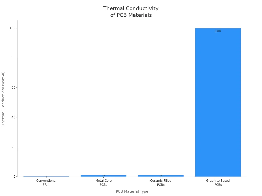
Thermal Conductivity
Thermal conductivity tells how well pcb materials move heat away from parts. This keeps parts from getting too hot and helps the board last longer. The table below shows how well different pcb materials move heat:
PCB Material Type | Typical Thermal Conductivity (W/m-K) | Impact on Heat Dissipation |
|---|---|---|
Conventional FR-4 | 0.2 to 0.4 | Low thermal conductivity makes it hard to move heat away in high-power circuits. |
Metal-Core PCBs | 1 to 4 | Metal core moves heat much better and helps keep things cool. |
Ceramic-Filled PCBs | 1 to 2 | Ceramic fillers help move heat better than regular boards. |
Graphite-Based PCBs | 100 to 400 | Very high thermal conductivity lets these boards move heat away fast, great for high-power jobs. |
Mechanical Strength
Mechanical strength is another important property for pcb materials. It shows how well a board can bend, stretch, or handle drops. FR-4 is strong and not expensive. Some new materials like CF 004 are even stronger and can take more heat. Boards with higher tensile and flexural strength last longer and do not break easily.
Signal Loss
Signal loss is about how well signals move through the board. Many things can cause signal loss:
Copper resistance and roughness
Dielectric losses from the dissipation factor
Impedance mismatches that cause reflections
Skin effect at high-frequency, which raises resistance
Fiberglass weave and design choices
Materials with low Dk and low loss tangent keep signals strong, especially in fast circuits.
Cost Factors
Material type: FR-4 is cheaper, but polyimide and metal-core cost more.
Copper thickness: Thicker copper works better but costs more.
Board size, number of layers, and how complex it is: More layers and tiny features need special tools and more time.
Surface finish: Simple finishes like HASL are cheaper than ENIG.
Picking the right pcb materials means you must balance important properties, signal quality, and cost for your project.
PCB Applications and Recommendations
Consumer Electronics
Consumer electronics use many types of PCB materials. Designers pick fr-4 a lot because it is cheap and strong. It also works for boards with many layers. Fr-4 is found in phones, tablets, and other daily gadgets. Aluminum PCBs are used when things get hot, like in LED lights and power supplies. PTFE is picked for devices that need to move data fast, like 5G phones and Wi-Fi parts.
PCB Material | Key Properties | Advantages | Limitations | Typical Applications |
|---|---|---|---|---|
fr-4 | Dielectric Constant ~4.5; Low thermal conductivity; Economical | Versatile, reliable, flame resistant | Low heat dissipation; Signal loss above 1 GHz | Smartphones, tablets, general electronics |
Aluminum PCB | High thermal conductivity; Metal base | Excellent heat dissipation | Limited to single-sided; Not ideal for high-frequency | LED lighting, power supplies |
High-Frequency Materials | Low dielectric constant; Stable across frequencies | Maintains signal integrity at high-frequency | Higher cost | 5G, Wi-Fi, fast data devices |
Tip: Fr-4 is usually the best choice for most consumer electronics because it is cheap and works well.
High-Frequency and RF
High-frequency and RF circuits need special materials to keep signals clear. PTFE and Rogers laminates are top picks because they lose less signal. These materials have low dielectric constants and loss tangents. This helps signals stay strong and steady. Ceramic PCBs also work well for high-frequency jobs, like in satellites and microwaves. Designers do not use fr-4 here because it loses too much signal above 1 GHz.
PTFE and ceramic-filled PTFE keep signal loss low.
Rogers laminates help signals stay steady and manage heat.
Important properties are low dielectric constant, low loss tangent, and good thermal conductivity.
For fast circuits, always check if the material can handle the needed frequency without losing signal quality.
Automotive and Industrial
Automotive and industrial electronics must survive tough places. They need PCB materials that can take heat, water, and shaking. Polyimide is great because it can handle up to 260°C. High-Tg fr-4 is also used a lot. PTFE and coated boards block water and chemicals. Ceramic and thick copper help with heat and big currents. Flexible materials like polyimide and PEN can bend and take hits.
Polyimide and high-Tg fr-4 work in hot places.
PTFE and coatings keep out water and chemicals.
Ceramic and thick copper help with heat and big currents.
Flexible PCBs can bend and handle shaking.
Designers often use special fr-4 types to meet rules and keep costs down while staying reliable.
Power and LED
Power and LED jobs need PCBs that move heat away fast. Metal-core PCBs, made with aluminum or copper, are best for this. They keep LEDs bright and stop them from getting too hot. Fr-4 is still used for less hard jobs. Ceramic PCBs are best for heat but cost more.
Metal-core PCBs are best for strong LEDs and power supplies.
Fr-4 is fine for normal LED products.
Ceramic PCBs are for the hottest jobs.
Important things are how well the board moves heat, works with electricity, and lasts long. Designers also want materials that do not burn and can handle water.
Aerospace and Defense
Aerospace and defense electronics need the safest and most reliable PCB materials. High-temperature laminates like FR408, Pyralux AP, and Nelco N7000-2HT are used a lot. These materials can take high heat and do not let out gas in space. Polyimide and PTFE-based laminates are picked for their strength and for working in tough places. Copper or aluminum bases help with heat. Special coatings and finishes like ENIG and HASL protect against water and shaking.
Material Type | Details |
|---|---|
Preferred Materials | |
Substrates | Copper or aluminum for better heat control |
Protective Coatings | Acrylic resin, ENIG, HASL |
Standards | MIL-PRF-50884, MIL-PRF-31032, AS9100, IPC-2610, ITAR regulations |
Aerospace and defense PCBs must follow strict rules for safety and quality.
Designers pick PCB materials based on what each job needs. The right choice keeps devices safe, working well, and lasting longer.
PCB Material Selection Guide
Decision Tree
Picking the right pcb material means knowing what your project needs. Engineers can use a simple decision tree to help choose:
First, think about what the device will do. Is it for home gadgets, fast circuits, or power tools?
Next, look at where it will be used. Will it get hot, wet, or shake a lot?
Then, check how fast signals need to move. Fast or RF circuits need materials with low dielectric constants.
Also, think about heat. Power and LED jobs need materials that move heat away well.
Last, look at your budget. Some materials cost more but work better.
Material | Key Properties | Typical Applications |
|---|---|---|
FR-4 | Cheap, strong, used in many ways | Most electronics, regular jobs |
Rogers | Low dielectric constant, good for fast signals | RF, wireless, microwave |
Polyimide | Handles high heat, bends easily | Flexible boards, hot places |
Metal Core | Moves heat away fast | LED lights, power supplies |
Ceramic | Strong, moves heat well | Space, defense, power electronics |
Teflon | Low dielectric constant, resists chemicals | Fast digital, RF, radar |
Selection Tips
A guide for picking materials should focus on what matters most:
Signal quality: Low dielectric constant keeps signals clear in fast circuits.
Price: FR-4 is good for most jobs and saves money.
Making the board: Polyimide is good for flexible boards, FR-4 is good for regular boards.
Safety: Some materials are safer and follow more rules.
What the device needs: Always pick a material that fits the job.
Testing: Try out a sample board before making a lot.
Tip: Engineers should always pick a pcb material that fits both the job and how the board will be made.
Common Mistakes
Engineers sometimes make mistakes when picking pcb materials:
Not thinking about how the board will be made and picking the wrong material.
Forgetting about heat, which can make the board too hot.
Picking a material just because it is cheap, not because it works best.
Not testing a sample board before making many.
Not checking if the material is safe or follows the rules.
Avoid these mistakes so the pcb works well and lasts a long time.
PCB Material Comparison Chart
Picking the best material for a circuit board is easier with a pcb material comparison chart. This chart helps engineers and students see how popular printed circuit board materials are different. The chart below compares fr-4, high-speed epoxy, polyimide, PTFE, metal core, and FR408HR. Each row shows an important property to make comparing simple.
Material | Dielectric Constant (Dk) | Thermal Conductivity (W/m·K) | Mechanical Strength | Cost | Typical Applications |
|---|---|---|---|---|---|
fr-4 | ~4.5 | 0.3–0.4 | Good | Low | Consumer electronics, general PCBs |
High-Speed Epoxy | 3.7–4.0 | 0.4–0.5 | Good | Medium | High-speed digital, telecom, aerospace |
Polyimide | 2.8–3.5 | 0.2 | Flexible, strong | High | Flex PCBs, harsh environments |
PTFE | ~2.1 | 0.3 | Moderate | High | RF, microwave, high-frequency circuits |
Metal Core | Varies (2–7) | 1.0–4.0+ | Varies, often strong | Medium | LED lighting, power, automotive |
FR408HR | ~3.65 | 0.4 | Good | Medium | Industrial, lead-free soldering, fast PCBs |
The pcb material comparison chart shows fr-4 is great for cost and reliability. PTFE works best for high-frequency jobs. Metal core boards move heat away better than others. Polyimide bends and handles heat well. High-speed epoxy and FR408HR help signals stay strong in advanced uses.
A material comparison chart helps you pick the right printed circuit board materials for each project. For example, fr-4 is good for most consumer devices. PTFE is the best choice for high-frequency work. Metal core boards are perfect for power and LED lighting. Polyimide is best for flexible or tough places. FR408HR and high-speed epoxy are used for fast signals and hard industrial jobs.
This chart gives engineers a quick way to compare pcb materials.
Using a material comparison chart helps you avoid mistakes and saves time.
Match the right pcb material to your job with this chart.
Tip: Always look at the material comparison chart before you start a new project. This easy step helps your board work better and saves money.
Picking the right PCB material changes how well a device works and how long it lasts. Important things to think about are dielectric constant, thermal conductivity, mechanical strength, and cost. Every project needs a material that fits what it needs. Designers should ask PCB manufacturers or experts for help with tricky jobs.
Good choices make electronics work better and last longer. Always look at material options and ask questions before you start. When you know more, you can choose with confidence!
FAQ
What is the most common PCB material?
FR-4 is used in most PCBs. It gives strong support and good insulation. Many electronics use FR-4 because it is reliable and not expensive.
Why do designers choose PTFE for high-frequency circuits?
Designers pick PTFE for high-frequency circuits because it has a low dielectric constant. Signals move quickly and stay clear. PTFE works well in RF, microwave, and 5G devices.
Tip: PTFE helps stop signal loss in fast electronic systems.
Can metal core PCBs handle high temperatures?
Metal core PCBs are great at moving heat away. Aluminum or copper cores help cool down parts. These boards are best for LED lights and power electronics.
How does the dielectric constant affect PCB performance?
A lower dielectric constant lets signals move faster. It helps keep signal quality high in fast circuits. Materials with a steady dielectric constant make boards more reliable.
Lower Dk: Good for high-speed and RF designs
Higher Dk: Used in regular electronics
See Also
The Importance Of Custom PCBA Manufacturing In Electronics
Benefits And Obstacles Of Flex PCBA In Electronics
Essential Factors To Consider When Selecting PCB Or PCBA
Emerging Trends Shaping PCB And PCBA Design And Manufacturing
Comprehensive Guide To PCBA Applications In Consumer Electronics